
Home security system

a home security and home security technology, applied in the field of home security systems, can solve the problems of not being able to make other cameras capture images, the location of capturing images cannot be varied, and the number of capturing images cannot be increased or decreased, so as to achieve the effect of easy confirmation of the alarm sta

Inactive Publication Date: 2003-05-29
SECURITY VIDEO CAMERA SYST INC
View PDF5 Cites 71 Cited by
  • Summary
  • Abstract
  • Description
  • Claims
  • Application Information

AI Technical Summary

Benefits of technology

[0011] Accordingly, since the updating unit updates said associations, it becomes possible to vary as well as increase and decrease the locations of capturing images according to the level and condition of monitoring.
[0013] Therefore, when configuring the system in an already constructed house, a plurality of the detection units, a plurality of the image capturing units and the control unit can be connected using electric power lines that are already established in the house. As a result, not only that the system can be configured easily, but the detection units and the image capturing units can be added quite easily.
[0015] Accordingly, since the image captured by the capturing unit is displayed on the image display unit, the state of alarm situations can be confirmed easily by viewing the images.

Problems solved by technology

However, in the conventional home security system, each of the sensors and cameras are always associated with each other according to certain relationships, and the locations for capturing images cannot be varied nor the number be increased or decreased according to the level and condition of monitoring.
As a result, even when the user, meaning the resident of the house, desires to have sufficient monitoring for going out, only one camera that is fixedly associated with a certain sensor captures images in the conventional home security system, and cannot make other cameras capture images.

Method used


Image

  • Home security system
  • Home security system
  • Home security system

Examples


Embodiment Construction

)

[0038] The following is an explanation of the home security system according to the embodiment of the present invention with reference to figures.

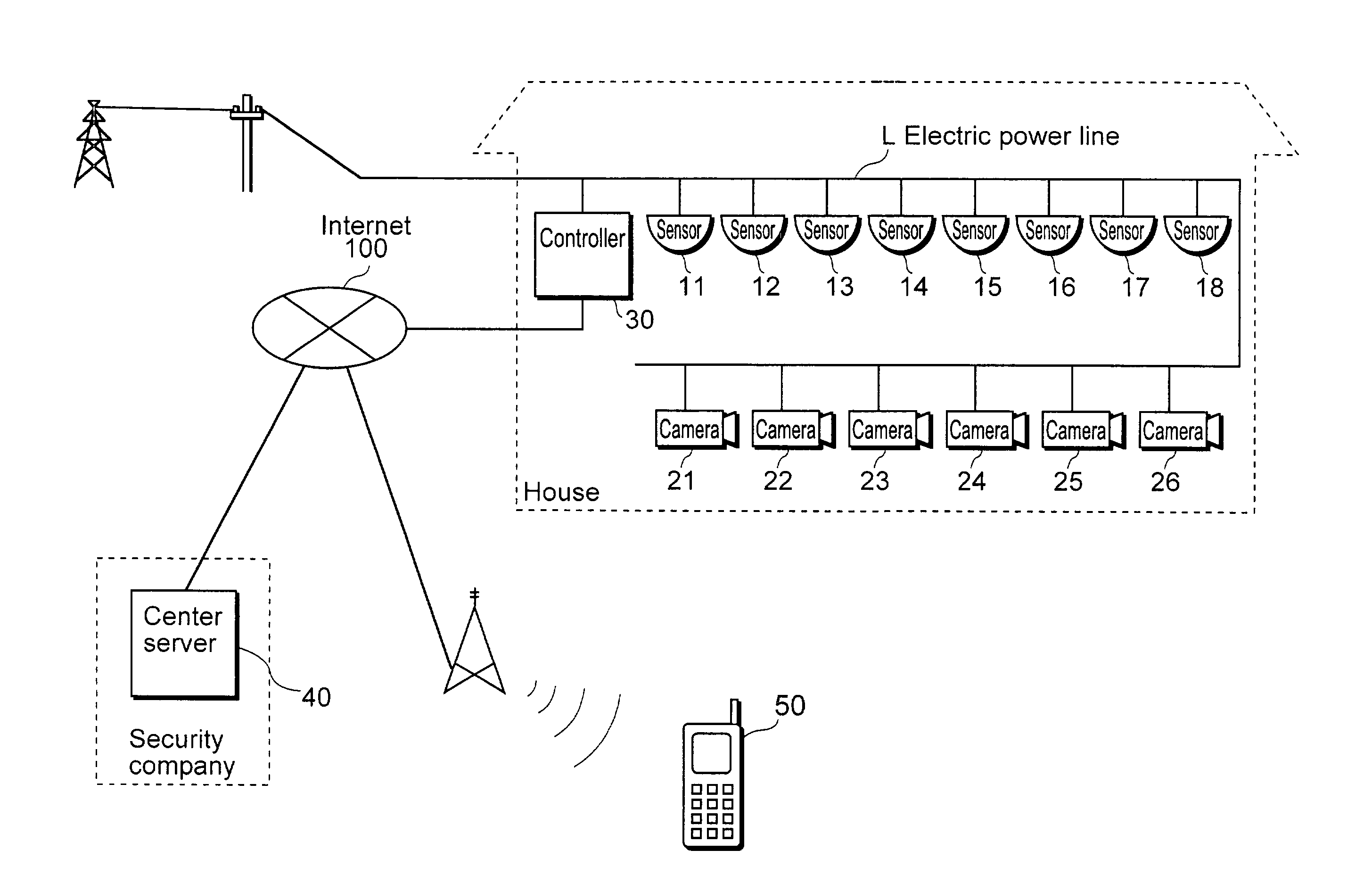
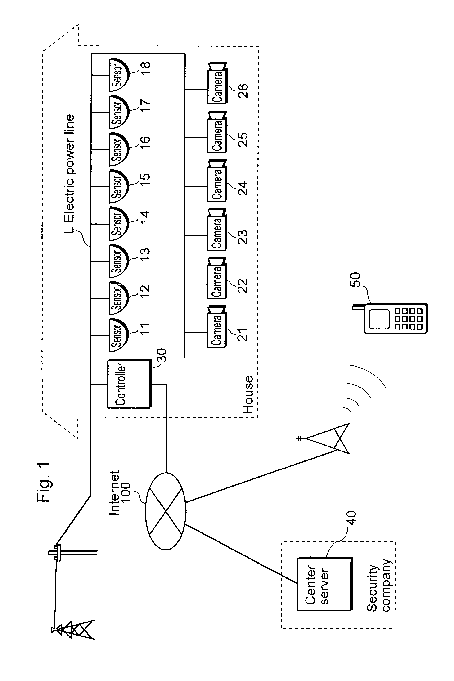
[0039] FIG. 1 is a constitutional diagram of the home security system according to the embodiment of the present invention.

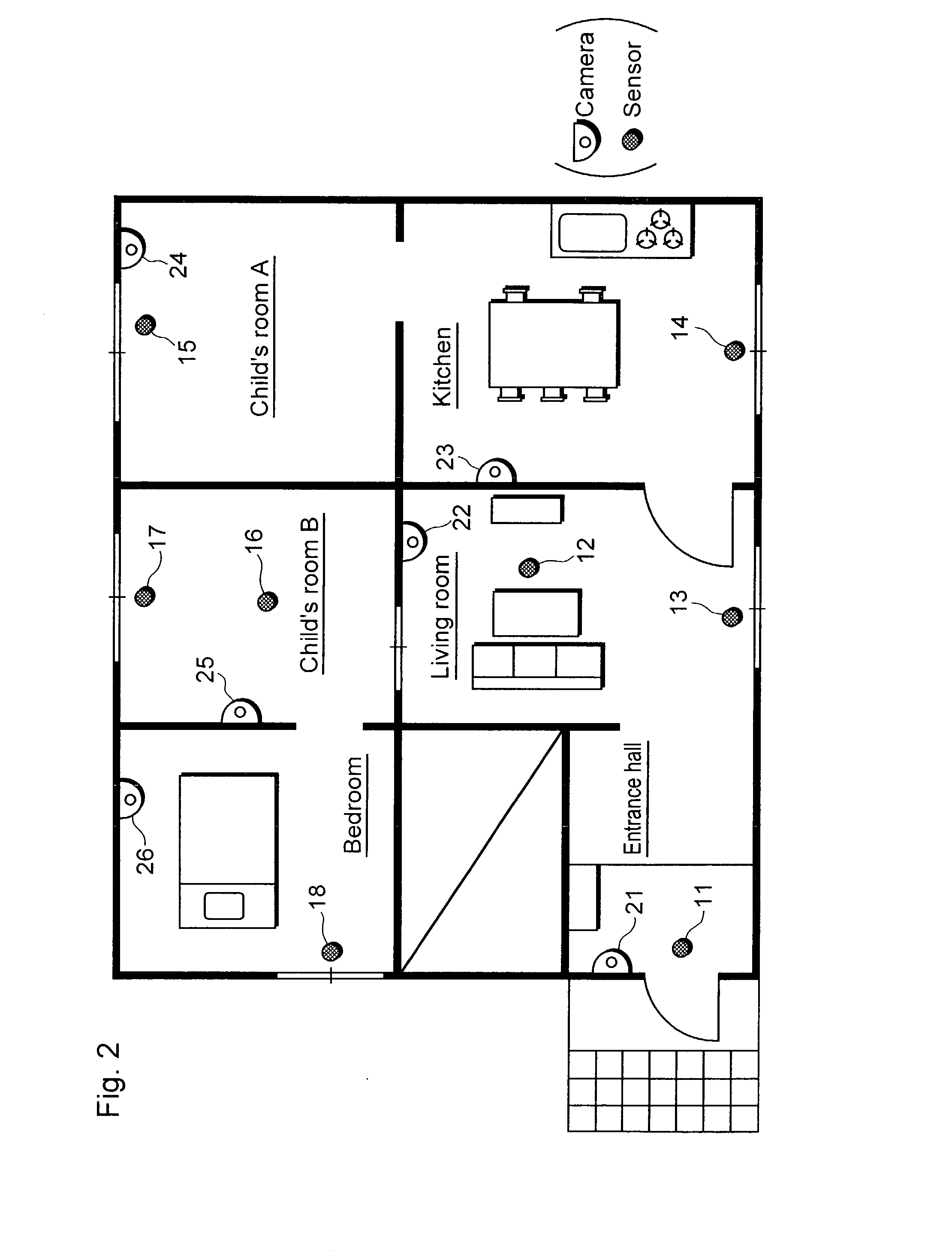
[0040] The home security system is a system that varies as well as increases and decreases the locations of capturing images according to the level and condition of monitoring. The system includes eight sensors 11 to 18 that detect the existence of human being, six cameras 21 to 26 that capture still images, a controller 30 that controls the cameras 21 to 26 according to the detection results of the sensors 11 to 18, a center server 40 that communicates with the controller 30 via the Internet 100, and a cellular phone 50.

[0041] The sensors 11 to 18, the cameras 21 to 26 and the controller 30 are installed within a house that is a target for monitoring, and transmit signals via electric power lines L that are establish...


PUM


Abstract

A home security system which includes sensors 11 to 18 that detect an alarming situation in different locations inside a facility, cameras 21 to 26 that capture images of different locations inside a facility, and a controller 30 that memorizes the associations between sensors 11 to 18 and cameras 21 to 26, and when any of the sensors 11 to 18 detects an alarming situation, has cameras that are associated with the sensors that have detected an alarming situation capture images based on the associations, and also updates the memorized associations.

Description

[0001] (1) Field of the Invention[0002] The present invention relates to a home security system that monitors the inside of a facility, and especially relates to a home security system that detects any occurrence of alarming situations and captures the images within a house or a facility by a camera.[0003] (2) Description of the Related Art[0004] So far, a home security system for monitoring the inside of a house has been proposed (see Japanese Laid-Open Patent Application No. H10-271572 as reference).[0005] The conventional home security system mentioned above includes a plurality of sensors that detect any intruder breaking in, a plurality of cameras that are installed within a house, and a control unit that controls the cameras according to the result of detection by the sensors.[0006] For example, when one of the aforementioned sensors detects an intruder breaking in, the control unit makes a camera that is fixedly associated with the sensor to capture the image, and sends the c...

Claims


Application Information

Patent Timeline
Patent Type & Authority Applications(United States)
IPC IPC(8): G08B13/196G08B15/00H04N7/18
CPCG08B13/19634G08B13/19645G08B13/19656G08B13/19663G08B13/19673H04N7/181G08B13/19682G08B13/19684G08B13/19695G08B25/06G08B13/1968H04N7/18
Inventor MURAKAMI, TAKASHISHINTANI, YASUYUKIAIZU, KAZUHIRO
Owner SECURITY VIDEO CAMERA SYST INC
Learn More