Home security system

a home security and home security technology, applied in the field of home security systems, can solve the problems of not being able to make other cameras capture images, the number of locations of capturing images cannot be increased or decreased, and the inability to vary the location of capturing images, so as to increase and decrease the locations of capturing images

Inactive Publication Date: 2004-07-06
SECURITY VIDEO CAMERA SYST INC
View PDF12 Cites 74 Cited by
  • Summary
  • Abstract
  • Description
  • Claims
  • Application Information

AI Technical Summary

Benefits of technology

is to provide a home security system that allows to vary as well as increase and decrease the locations of capturing images according to the level and condition of monitoring.
Therefore, when configuring the system in an already constructed house, a plurality of the detection units, a plurality of the image capturing units and the control unit can be connected using electric power lines that are already established in the house. As a result, not only that the system can be configured easily, but the detection units and the image capturing units can be added quite easily.
Accordingly, since the image captured by the capturing unit is displayed on the image display unit, the state of alarm situations can be confirmed easily by viewing the images.

Problems solved by technology

However, in the conventional home security system, each of the sensors and cameras are always associated with each other according to certain relationships, and the locations for capturing images cannot be varied nor the number be increased or decreased according to the level and condition of monitoring.
As a result, even when the user, meaning the resident of the house, desires to have sufficient monitoring for going out, only one camera that is fixedly associated with a certain sensor captures images in the conventional home security system, and cannot make other cameras capture images.

Method used


Image

  • Home security system
  • Home security system
  • Home security system

Examples


case 200d

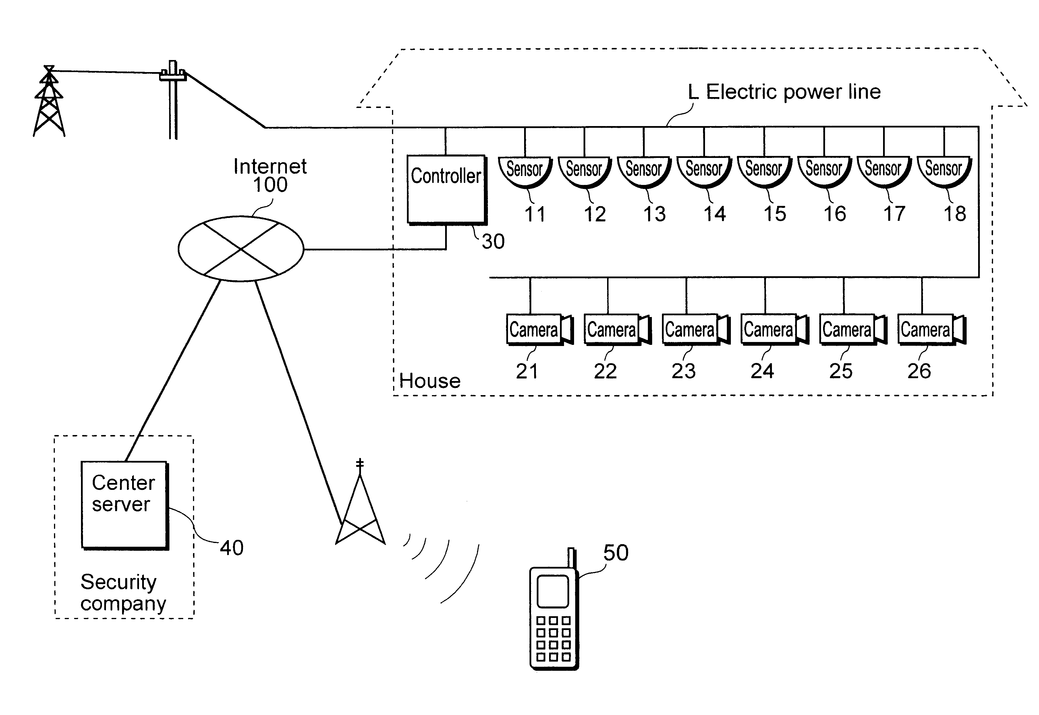
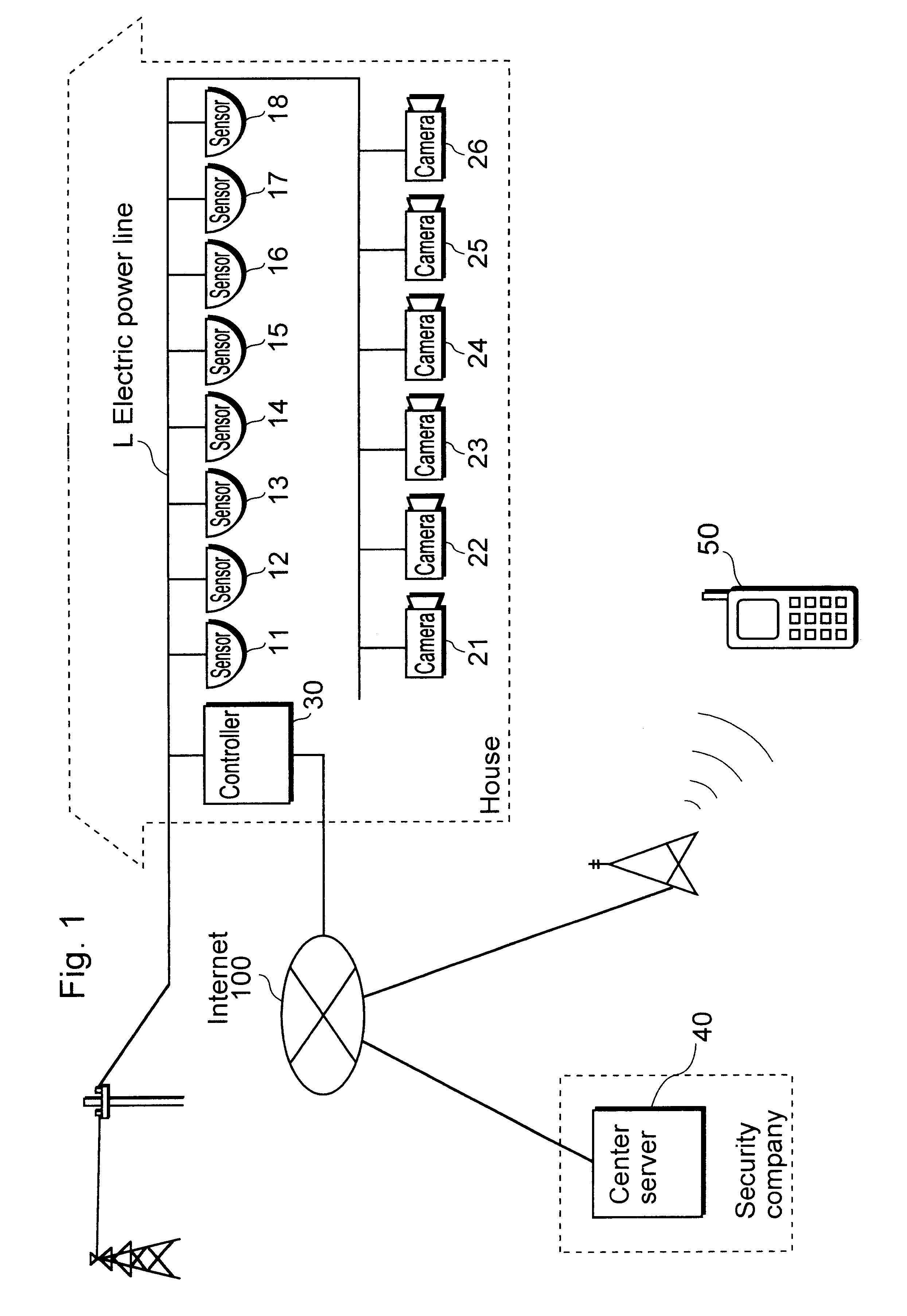
the camera 210 is, as shown in FIG. 17 and similar to the case 20d of the cameras 21 to 26, shaped as a nearly rectangular box. At the front side of the case 200d are a protruding part 20da and an opening part 20db, and a window 202 for exposing the camera display unit 202a as well as an expose window 201 for exposing the push-button switch 201b are also formed.

The camera operation unit 203 outputs a signal according to the operation of the push-button switch 201b to the communication control unit 200c, and every time the communication control unit 200c receives the signal, it outputs a mode switching signal that directs to switch the mode to the controller 30 via the electric power lines L.

The main control unit 38 of the controller 30 obtains the mode switching signal via the electric power line communication unit 31, and switches the modes that are set in the order of "Not home mode".fwdarw."At home mode".fwdarw."User setting mode 1".fwdarw."User setting mode 2".fwdarw."User setti...


PUM


Abstract

A home security system which includes sensors 11 to 18 that detect an alarming situation in different locations inside a facility, cameras 21 to 26 that capture images of different locations inside a facility, and a controller 30 that memorizes the associations between sensors 11 to 18 and cameras 21 to 26, and when any of the sensors 11 to 18 detects an alarming situation, has cameras that are associated with the sensors that have detected an alarming situation capture images based on the associations, and also updates the memorized associations.

Description

(1) Field of the InventionThe present invention relates to a home security system that monitors the inside of a facility, and especially relates to a home security system that detects any occurrence of alarming situations and captures the images within a house or a facility by a camera.(2) Description of the Related ArtSo far, a home security system for monitoring the inside of a house has been proposed (see Japanese Laid-Open Patent Application No. H10-271572 as reference).The conventional home security system mentioned above includes a plurality of sensors that detect any intruder breaking in, a plurality of cameras that are installed within a house, and a control unit that controls the cameras according to the result of detection by the sensors.For example, when one of the aforementioned sensors detects an intruder breaking in, the control unit makes a camera that is fixedly associated with the sensor to capture the image, and sends the captured image data to an external home car...

Claims


Application Information

Patent Timeline
Patent Type & Authority Patents(United States)
IPC IPC(8): G08B15/00H04N7/18G08B13/196
CPCG08B13/19634G08B13/19645G08B13/19656G08B13/19663G08B13/19673G08B13/1968G08B13/19682G08B13/19684G08B13/19695G08B25/06H04N7/181H04N7/18
Inventor MURAKAMI, TAKASHISHINTANI, YASUYUKIAIZU, KAZUHIRO
Owner SECURITY VIDEO CAMERA SYST INC
Why Eureka
Try Eureka