Method of manufacturing a differentially heat treated catheter guide wire

a technology of heat treatment and guide wire, which is applied in the direction of guide wire, catheter, diagnostic recording/measuring, etc., can solve the problems of manual operation kinking of guide wires, easy plastic deformation, and rendering the smooth introduction operation of catheter impossibl

Inactive Publication Date: 2000-03-28
TERUMO KK
View PDF30 Cites 70 Cited by
  • Summary
  • Abstract
  • Description
  • Claims
  • Application Information

AI Technical Summary

Benefits of technology

Furthermore, according to the present invention, there is provided a method of manufacturing a catheter guide wire fabricated by using an elastic alloy wire as a base material, characterized in that a leading end side of the base material is divided into a plurality of areas, and a heat treatment is performed by changing the temperatures and time in units of the areas so that the flexibility of the base material is sequentially increased from the proximal to distal end portion of the leading end side.
In a conventional catheter guide wire, a diameter at a proximal end portion of a wire member made of an elastic alloy or a very elastic alloy is merely increased, and a diameter at its distal end portion is relatively decreased, thereby making the proximal end portion rigid and the distal end portion flexible. Unlike such a conventional catheter guide wire, according to the present invention, a wire member is subjected to a heat treatment by sequentially changing the confunction along its longitudinal direction. As a result, the physical characteristics of the wire member can be set in an ideal state as a catheter guide wire.

Problems solved by technology

However, plastic deformation can easily occur in these conventional guide wires, and some manual operation can kink the guide wires.
A kinked portion becomes an obstacle during introduction of a catheter, thus rendering smooth introduction operation of a catheter impossible as well as greatly degrading its torque transmitting performance.
Therefore, such a guide wire cannot be easily broken during operation and will not easily attain a bending tendency.
However, such guide wire has a high elasticity at its distal end portion and is thus infavorable in terms of flexibility.
Then the diameter of its proximal end portion is 0.5 mm or less, the rigidity is insufficient and the torque transmitting performance is poor.

Method used


Image

  • Method of manufacturing a differentially heat treated catheter guide wire
  • Method of manufacturing a differentially heat treated catheter guide wire
  • Method of manufacturing a differentially heat treated catheter guide wire

Examples


Embodiment Construction

Preferred embodiments of the present invention will be described with reference to the accompanying drawings.

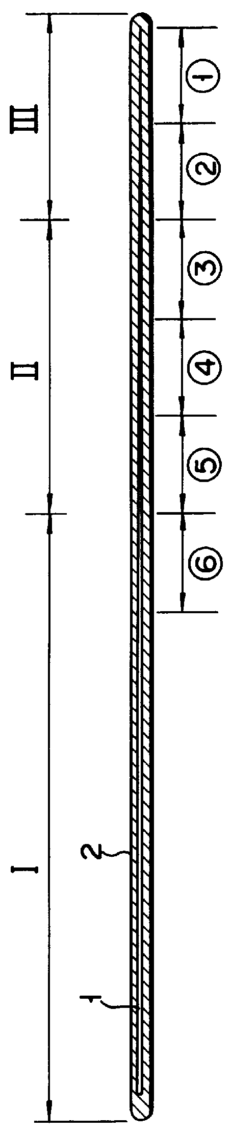
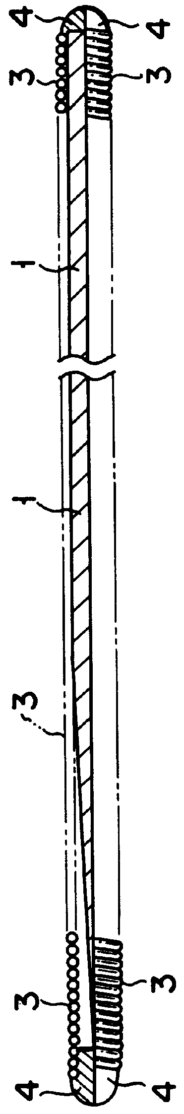
FIG. 1 is a sectional view of a catheter guide wire taken along the longitudinal direction according to an embodiment of the present invention. Referring to FIG. 1, reference numeral 1 denotes a core member; and 2, a thermoplastic resin layer entirely covering core member 1.

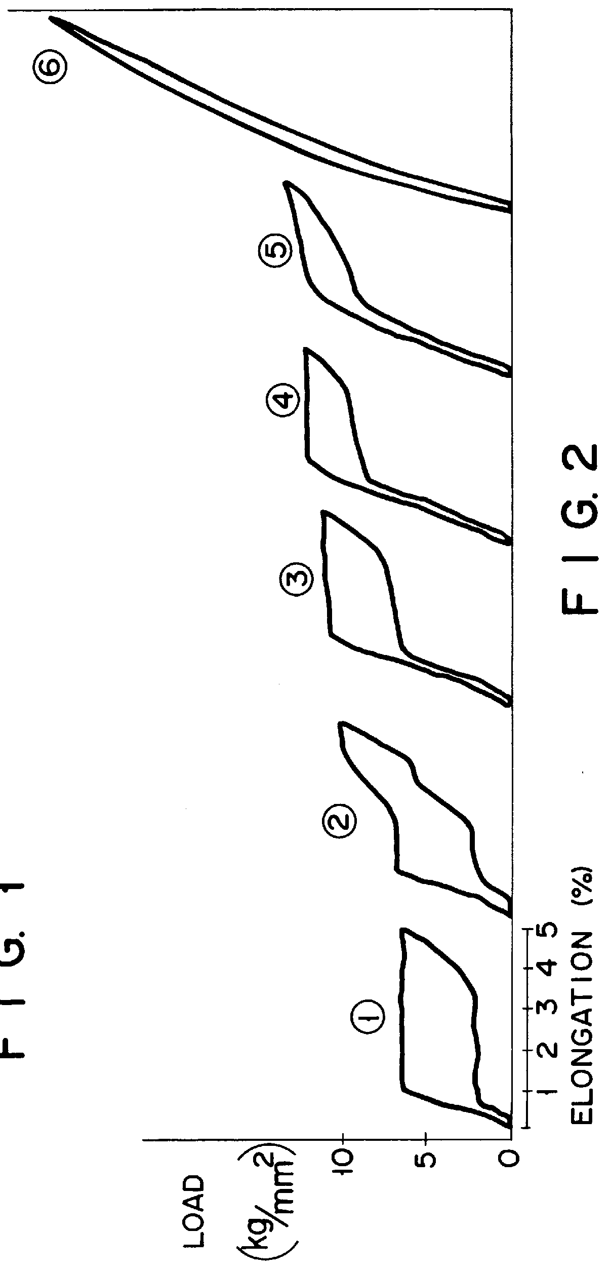
Core member 1 is a wire member made of an elastic alloy wire such as a piano wire, and preferably a very elastic alloy such as an Ni-Ti alloy. Core member 1 can have a uniform diameter of 0.2 to 0.4 mm, or can be tapered toward its distal end such that the diameter at its proximal end portion is 0.2 to 0.4 mm and the diameter at its distal end portion is 0.01 to 0.1 mm. In this specification, a very elastic alloy is defined as an alloy whose recoverable elastic strain is as large as several % to more than ten % and whose stress level does not exceed a predetermined value even if the strain is increased. Th...


PUM

PropertyMeasurementUnit
temperatureaaaaaaaaaa
outer diameteraaaaaaaaaa

Abstract

A catheter guide wire is provided for guiding a catheter into a body cavity such as a blood vessel. The base material constituting the wire is made of an elastic alloy wire and subjected to a heat treatment such that its flexibility is sequentially increased from its proximal to distal end portions. A thermoplastic resin or/and a coil spring can be applied to at least the distal end portion of the wire base material. A method of manufacturing the catheter guide wire is also provided. The method is characterized in that the leading end side of the base material is divided into a plurality of areas and subjected to a heat treatment by changing the heat treatment temperature and the time conditions in units of the areas so that the flexibility of the base material is sequentially increased from the proximal to distal end portions of the leading end side.

Description

TECHNICAL FIELDThe present invention relates to a catheter guide wire for guiding a clinical or testing catheter to a predetermined portion of a body cavity such as a blood vessel, a digestive tract, and a windpipe and holding it therein, and a method of manufacturing the same.PRIOR ARTWhen a catheter is to be guided to a branching peripheral portion of a blood vessel or the like, first, a guide wire must be guided to a target portion. In this case, since a target portion is generally thin and thus tends to be easily damaged, the distal end portion of the guide wire must be flexible so that it will not damage a blood vessel wall, will follow the shape of the blood vessel well even if the blood vessel is curved, and can be inserted in a complex branching blood vessel. Meanwhile, the proximal end portion of the guide wire must have torque transmitting performance so that a manual operation performed at the proximal end portion is transmitted to the distal end portion. Thus, the proxim...

Claims


Application Information

Patent Timeline
Patent Type & Authority Patents(United States)
IPC IPC(8): A61M23/00
CPCA61M25/09A61M2025/09083A61M2025/09141
Inventor SAGAE, KYUTASUGIYAMA, YOSHIAKI
Owner TERUMO KK
Why Eureka
Try Eureka