Offset remote center manipulator for robotic surgery

a robotic surgery and remote center technology, applied in the field of robotic surgical robotics, to achieve the effect of enhancing the efficiency and ease of use, reducing the overall complexity, size and physical weight of the robotic surgical system, and enhancing the range of instrument movemen

Active Publication Date: 2009-09-29
INTUITIVE SURGICAL OPERATIONS INC
View PDF70 Cites 591 Cited by
  • Summary
  • Abstract
  • Description
  • Claims
  • Application Information

AI Technical Summary

Benefits of technology

[0007]The present invention is generally related to medical, surgical, and / or robotic devices and systems. In particular, the present invention is directed to improved remote center manipulators used to support a surgical instrument and provide a center of spherical rotation, remote from any bearings or mechanical supports, at a desired location of the instrument during minimally invasive robotic surgery. The remote center manipulator constrains the instrument to move around a fixed center of rotation, which is preferably coincident with an entry incision in a patient, such as the patient's abdominal wall. In an exemplary embodiment, the invention provides an offset remote center parallelogram manipulator linkage assembly which constrains a position of a surgical instrument during minimally invasive robotic surgery. The improved remote center manipulator advantageously enhances the range of instrument motion along first and second axes while at the same time reduces the overall complexity, size, and physical weight of the robotic surgical system. Such advantages in turn enhance the efficiency and ease of use of such robotic surgical systems.
[0009]The first side of the parallelogram is angularly offset from the first axis by at least 2 degrees, preferably by 10 degrees. Generally, the first side of the parallelogram is angularly offset from the first axis in a range from about 2 degrees to about 45 degrees, preferably in a range from about 2 degrees to about 35 degrees. The first side of the parallelogram may sometimes extend beneath the first axis, generally at least one side of the parallelogram extends beneath the first axis. The manipulator provides an improved range of shaft motion that is greater than ±90 degrees along the first axis, preferably greater than ±95 degrees along the first axis. In particular, the cantilevered parallelogram linkage base provides shaft motion in a range from ±168 degrees along the first axis, wherein the first axis is sometimes referred to as a yaw axis. Advantageously, the offset articulate linkage assembly provides an improved range of shaft motion that is greater than ±55 degrees along a second axis, preferably greater than ±60 degrees along the second axis. Generally, the offset articulate linkage assembly provides improved shaft motion in a range from ±75 degrees along the second axis, wherein the second axis is sometimes referred to as a pitch axis.
[0010]Preferably, at least one of the links is bent at an angle so as to provide clearance for another link to rest on the bent link. This clearance prevents inter-linkage collisions so as to further allow for an improved range of pitch motion. For example, the link may be bent at an angle of about 22 degrees. The manipulator may not be balanced in at least one degree of freedom. As such, a brake system may be coupled to the articulate linkage assembly. The brake system releasably inhibits articulation of at least one of the joints. Preferably, the plurality of links and joints comprise at least one pulley and at least one flexible element coupled to the pulley that is configured to constrain shaft motion relative to the center of rotation. In one embodiment, the plurality of links and joints comprise a linkage having six pulleys and four belts. The plurality of links and joints are driven by a servomechanism. The plurality of links and the parallelogram linkage base may be offset in different planes so as to reduce the possibility of inter-linkage collisions. The plurality of links and the instrument holder however may be located in the same plane.
[0011]In general, the articulate linkage assembly is configured to constrain shaft motion relative to the center of rotation. As such, the shaft is maintained substantially aligned through the center of rotation as the shaft is pivotally moved in at least one degree of freedom. Preferably, the center of rotation is aligned with the incision point to the internal surgical site, for example, with a trocar or cannula at an abdominal wall during laparoscopic surgery. As such, an end effector of the surgical instrument can be positioned safely by moving the proximal end of the shaft using the offset remote center robotic manipulator without imposing dangerous forces against the abdominal wall.
[0013]The first pivot of the parallelogram is angularly offset from the first axis by at least 2 degrees, preferably by 10 degrees. Generally, the first pivot of the parallelogram is angularly offset from the first axis in a range from about 2 degrees to about 45 degrees, preferably in a range from about 2 degrees to about 35 degrees. The first pivot of the parallelogram may sometimes extend beneath the first axis, generally at least one pivot of the parallelogram extends beneath the first axis. The manipulator provides shaft motion in a range greater than ±90 degrees along the first axis, preferably greater than ±95 degrees along the first axis. In particular, the cantilevered parallelogram linkage base provides improved shaft motion in a range from ±168 degrees along the first axis, e.g., yaw axis. Advantageously, the offset parallelogram and bent link together provide shaft motion in a range greater than ±55 degrees along a second axis, preferably greater than ±60 degrees along the second axis. Typically, the offset parallelogram and bent link provide improved shaft motion in a range from ±75 degrees along the second axis, e.g., pitch axis.
[0017]In still another aspect of the present invention, a method for performing minimally invasive robotic surgery within a body cavity of a patient employing a surgical instrument is provided. The surgical instrument coupleable to an instrument holder during minimally invasive robotic surgery includes an elongate shaft. The shaft has a distal working end configured for insertion through an incision in a body wall into a body cavity of a patient. The method comprises providing an offset articulate linkage assembly as described above. At least the distal working end of the instrument shaft is introduced through the incision into the body cavity. At least the shaft of the instrument is pivotally moved in at least one degree of freedom while at least a portion of the distal working end is within the body cavity. The offset articulate linkage assembly constrains lateral motion of the shaft to pivotal motion about the center of rotation so that the shaft is maintained substantially aligned through the center of rotation.

Problems solved by technology

While many of the surgeries performed each year in the United States could potentially be performed in a minimally invasive manner, only a portion of the current surgeries use these advantageous techniques due to limitations in minimally invasive surgical instruments and the additional surgical training involved in mastering them.

Method used


Image

  • Offset remote center manipulator for robotic surgery
  • Offset remote center manipulator for robotic surgery
  • Offset remote center manipulator for robotic surgery

Examples


Embodiment Construction

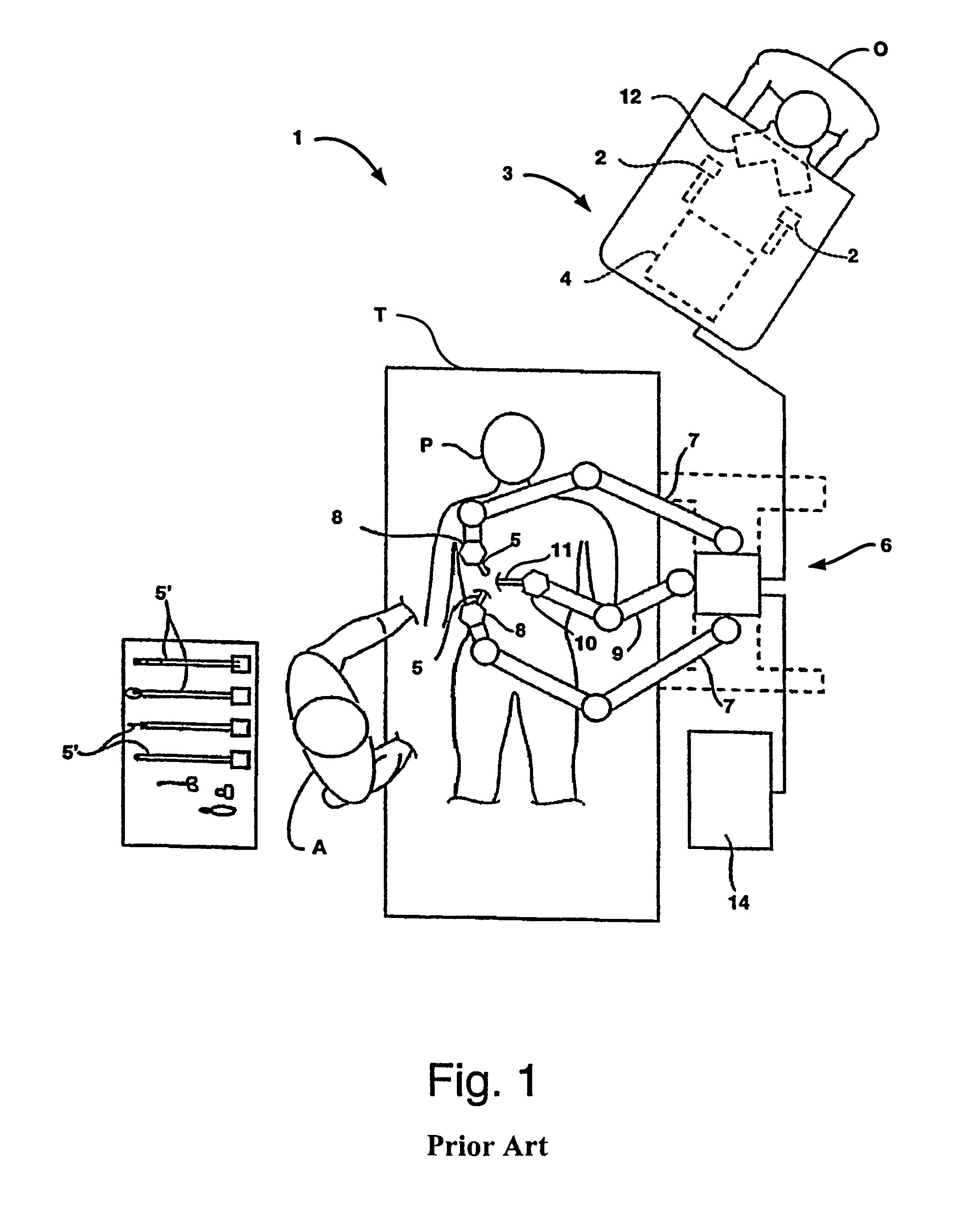
[0029]FIGS. 1 through 4 illustrate a robotic surgical system 1 for performing minimally invasive robotic surgery, which is described in more detail in U.S. Pat. No. 6,246,200. An operator O (generally a surgeon) performs a minimally invasive surgical procedure on patient P lying on operating table T, the operator O manipulating one or more input devices or masters 2 at a surgeon's console 3. In response to the surgeon's inputs, a computer processor 4 of console 3 directs movement of endoscopic surgical instruments or tools 5, effecting servo-mechanical movement of the instruments via a robotic patient-side system 6 (a cart-mounted system in this example).

[0030]Typically, patient side system or cart 6 includes at least three robotic manipulator arms. Two arms or linkages 7 (mounted at the sides of cart 6 in this example) support and position servo-manipulators 8 which drive surgical tools 5; and one arm or linkage 9 (mounted at the center of cart 6 in this example) supports and posit...


PUM


Abstract

Medical, surgical, and / or robotic devices and systems often including offset remote center parallelogram manipulator linkage assemblies which constrains a position of a surgical instrument during minimally invasive robotic surgery are disclosed. The improved remote center manipulator linkage assembly advantageously enhances the range of instrument motion while at the same time reduces the overall complexity, size, and physical weight of the robotic surgical system.

Description

BACKGROUND OF THE INVENTION[0001]The present invention is generally related to medical, surgical, and / or robotic devices and systems. In an exemplary embodiment, the invention provides offset remote center manipulators which constrain a position of a surgical instrument during minimally invasive robotic surgery.[0002]Minimally invasive medical techniques are intended to reduce the amount of extraneous tissue which is damaged during diagnostic or surgical procedures, thereby reducing patient recovery time, discomfort, and deleterious side effects. One effect of minimally invasive surgery, for example, is reduced post-operative hospital recovery times. Because the average hospital stay for a standard surgery is typically significantly longer than the average stay for an analogous minimally invasive surgery, increased use of minimally invasive techniques could save millions of dollars in hospital costs each year. While many of the surgeries performed each year in the United States coul...

Claims


Application Information

Patent Timeline
Patent Type & Authority Patents(United States)
IPC IPC(8): A61B17/00
CPCA61B19/2203A61B19/5212A61B2019/2223A61B2019/2234Y10T74/20305A61B2019/265A61B2017/00477Y10S901/15A61B2019/2242A61B17/00234A61B2090/506A61B34/71A61B90/361A61B34/30A61B34/37A61B2034/305
Inventor COOPER, THOMAS G.SOLOMON, TODD R.
Owner INTUITIVE SURGICAL OPERATIONS INC
Why Eureka
Try Eureka