Medical manipulator

a technology of manipulators and working units, applied in the field of medical manipulators, can solve the problems of complex structure of medical manipulators with distal-end working units movable with more degrees of freedom, and achieve the effect of complex structure and smoking surgical techniques

Active Publication Date: 2016-05-24
KARL STORZ GMBH & CO KG
View PDF12 Cites 544 Cited by
  • Summary
  • Abstract
  • Description
  • Claims
  • Application Information

AI Technical Summary

Benefits of technology

[0005]It is desirable for medical manipulators to have an increased number of degrees of freedom and as wide a movable range as possible for a distal-end working unit including an end effector. For example, if the distal-end working unit can roll in an unlimited angular range, then the medical manipulator is expected to contribute to smoother surgical techniques such as a tie-knotting or ligating technique. However, a medical manipulator with a distal-end working unit movable with more degrees of freedom tends to be more complex in structure.

Problems solved by technology

However, a medical manipulator with a distal-end working unit movable with more degrees of freedom tends to be more complex in structure.

Method used


Image

  • Medical manipulator
  • Medical manipulator
  • Medical manipulator

Examples


first embodiment

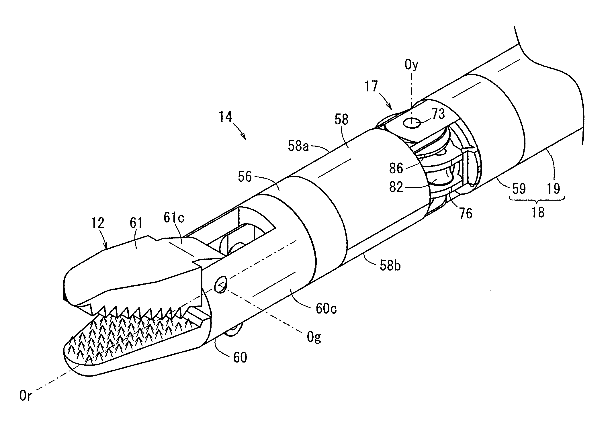
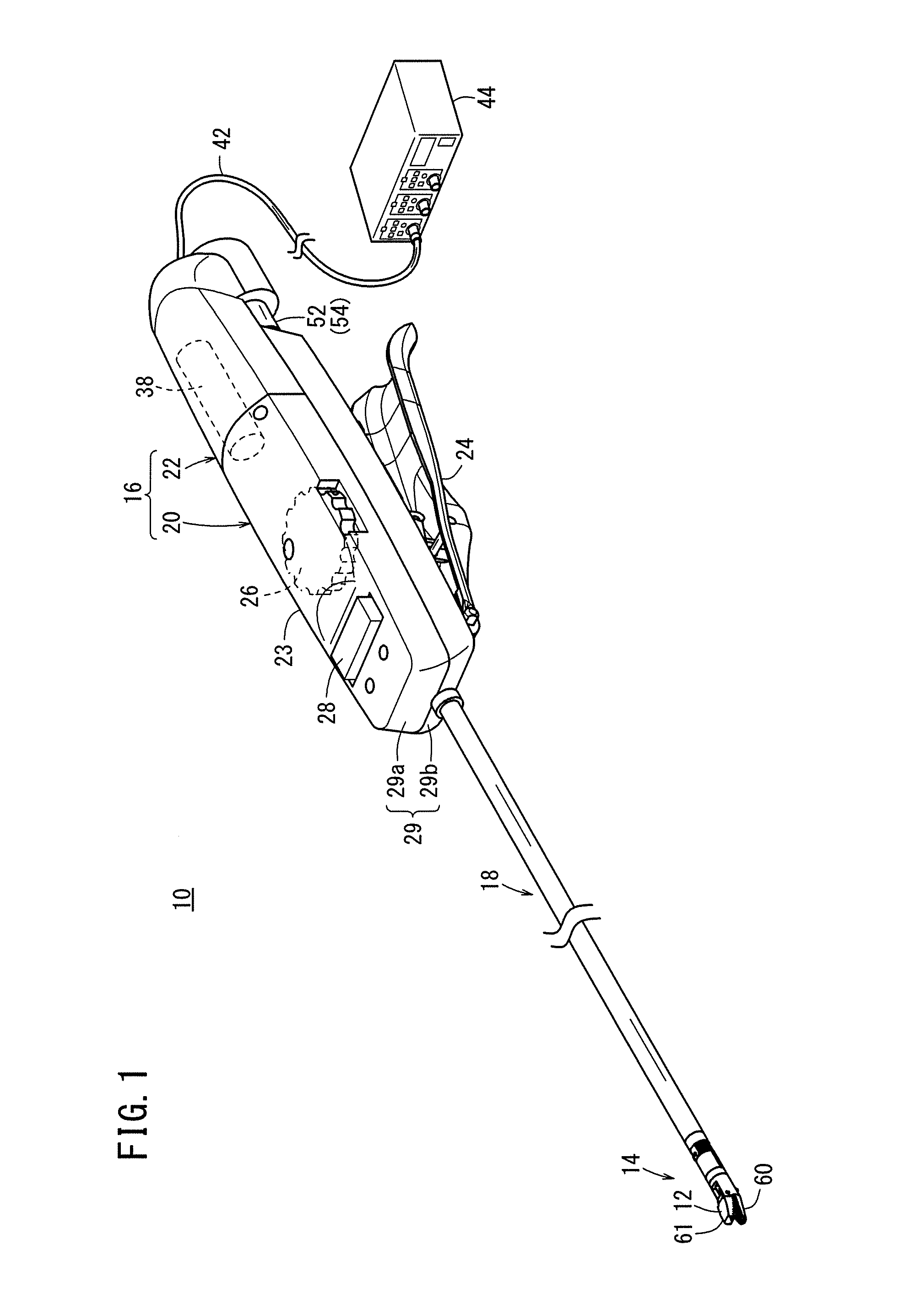
[0033]FIG. 1 shows in perspective, partly omitted from illustration, a medical manipulator 10 according to a first embodiment of the present invention. As shown in FIG. 1, the medical manipulator 10 is a medical device having an end effector 12 on its distal end for gripping a needle, a suture, or a portion of a biological body or touching a biological body and treating the biological body. Depending on the type of the end effector 12, the medical manipulator 10 may be constituted as a needle driver, a pair of gripping forceps, a monopolar electrosurgical scalpel, a bipolar electrosurgical scalpel, or the like.

[0034]The general structure of the medical manipulator 10 which is constituted as a needle driver will first be described below, and then the constitutive details of the medical manipulator 10 will be described thereafter.

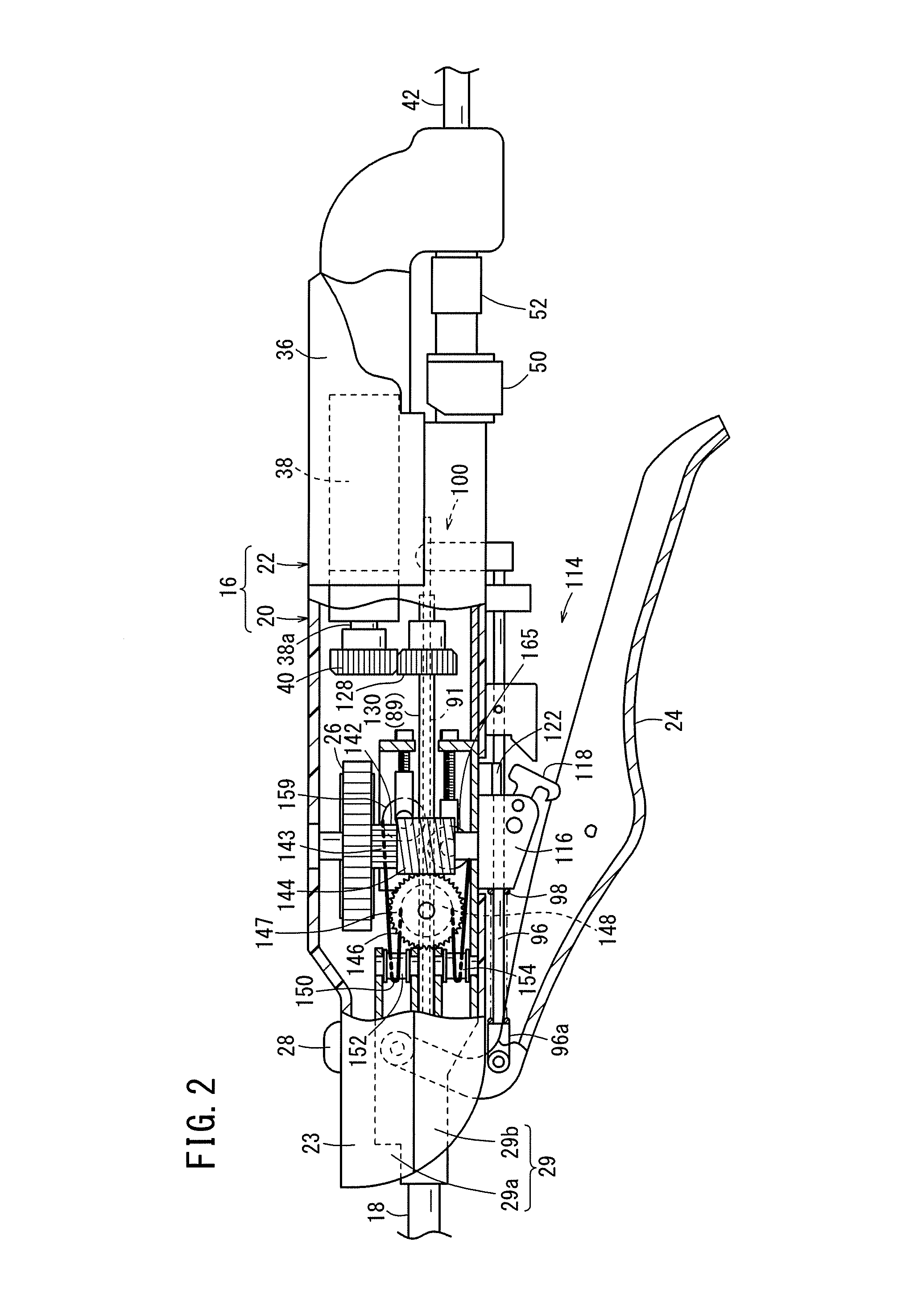
[0035]The medical manipulator 10 has a distal-end working unit 14 including the end effector 12, a handle 16 for actuating the end effector 12, and a shaft 1...

second embodiment

[0099]FIG. 7 shows in perspective, partly omitted from illustration, a medical manipulator 200 according to a second embodiment of the present invention. The medical manipulator 200 is used in surgical techniques in endoscopic surgical operations, for example, to treat, e.g., cauterize by heating, a biological tissue as an object X to be treated. The biological tissue as the object X to be treated may be a tumor (lesion), a muscle, a blood vessel, a nerve, or the like, for example. The medical manipulator 200 has an end effector 212 (electrosurgical scalpel) which grips a biological tissue and supplies an electric current to the biological tissue.

[0100]As shown in FIG. 7, the medical manipulator 200 has a distal-end working unit 214 including the end effector 212 for treating a biological tissue, a shaft 216 connected to the proximal end of the distal-end working unit 214 and extending over a predetermined length of about 350 mm, for example, toward the proximal end of the medical m...


PUM


Abstract

A medical manipulator has a distal-end working unit including an end effector. The distal-end working unit has a rotor having a hollow tube rotatable in unison with the end effector and a rotational support tube having a posture variable with respect to the shaft. The rotor is rotatably supported by an inner circumferential surface of the rotational support tube. Engaging members that are disposed in side holes formed in the rotational support tube have inner ends inserted in an annular groove.

Description

FIELD OF THE INVENTION[0001]The present invention relates to a medical manipulator for use in surgical operations, especially endoscopic surgical operations, and more particularly to a medical manipulator that includes an end effector in a distal-end working unit which can be rolled in an unlimited angular range.BACKGROUND OF THE INVENTION[0002]In endoscopic surgery, also known as laparoscopic surgery, the surgeon makes a plurality of incisions in the abdominal region or the like of the patient, places respective trocars or tubular instruments in the incisions, and inserts a laparoscope (camera) and a plurality of pairs of forceps through the trocars into the body cavity to access the target region. Grippers for gripping a biological tissue or the like, scissors, electrosurgical scalpel blades, or the like are mounted as end effectors on the distal end portions of the forceps.[0003]After having inserted the laparoscope and the forceps into the body cavity, the surgeon performs a sur...

Claims


Application Information

Patent Timeline
Patent Type & Authority Patents(United States)
IPC IPC(8): A61B17/00A61B17/29
CPCA61B17/29A61B2017/00314A61B2017/00398A61B2017/2929A61B2090/306A61B2017/293A61B2034/305A61B2034/306
Inventor ISHIDA, SHINJISANO, HIROAKISUZUKI, TSUNEYOSHIFUKUDA, JUNICHI
Owner KARL STORZ GMBH & CO KG
Why Eureka
Try Eureka