Low back pain treatment tool

a low back pain and tool technology, applied in the field of low back pain treatment tools, can solve the problems of excessive correction and designed pelvis correction, and achieve the effects of restoring the downward movement of the spine, and reducing the length of the cylinder casing

Inactive Publication Date: 2014-12-30
TAGUCHI HIROSHI +1
View PDF8 Cites 2 Cited by
  • Summary
  • Abstract
  • Description
  • Claims
  • Application Information

AI Technical Summary

Benefits of technology

[0017]According to the invention set forth in claim 1, riding on the coccyx contact treatment member of the low back pain treatment tool in a “standing position” can restore the downward movement of the spine by upward vertical compression from immediately below the coccyx using the “weight of the recipient”.
[0018]Treating a recipient in a “standing position” can allow positional correction of the sacrum, ilium, coccyx, or the like, or more specifically, correction of the pelvis constituted thereby, in a stable state for the lumbar vertebra, making it possible to continuously relieve low back pain.
[0019]By vertically vibrating the coccyx contact treatment member which is slidably placed through the elastic member, while riding on it, a recipient can finely adjust the position of the coccyx contact treatment member at the pelvis, so that he / she can achieve pelvis correction at a proper position.
[0020]According to the invention set forth in claim 2, the cylinder casing is fixed and supported on the posture holding member by fixing the cylinder casing on the upper surface of the horizontal seat plate provided at a proper height, the length of the cylinder casing can be reduced. This prevents excessive moment force from being applied to the bolt which is located at the basal portion of the cylinder casing to fix it, thereby reducing the occurrence of failures. In addition, shorter length of the cylinder casing can save on costs.
[0021]According to the invention set forth in claim 3, by providing the pair of left and right side surface plates fixed orthogonally to the horizontal seat plate and the posture holding surface of the posture holding member, the orientation of the horizontal seat plate can be kept constant even under load of the weight of the recipient.
[0022]According to the invention set forth in claim 4, the rectangular parallelepiped foot rest blocks are stably provided in place at the corner portions, which are formed by three surfaces consisting of the outer surface of either of the side plates, the horizontal surface of the base plate, and the posture holding surface, so that the blocks can simultaneously come into contact with the surfaces. Thereby the recipient can more easily apply his / her weight to the coccyx contact treatment member in a “standing position” while riding on the treatment tool. More specifically, he / she can thereby appropriately select and easily adjust the height at which he / she can take his / her feet off the foot rest blocks while riding on the treatment tool, and can also make height adjustment in accordance with his / her height, before he / she uses the treatment tool.

Problems solved by technology

These devices should be used on a recipient who is in a sitting position, a supine position, or the like, and are not designed for correcting the pelvis while he / she raises his / her body up, or more specifically, is in a “standing position” which is a stable state for the lumbar vertebra.
In addition, the use of a mechanical device such as a motor may lead to excessive correction depending on how it is used.

Method used


Image

  • Low back pain treatment tool
  • Low back pain treatment tool
  • Low back pain treatment tool

Examples


embodiment 1

(Embodiment 1)

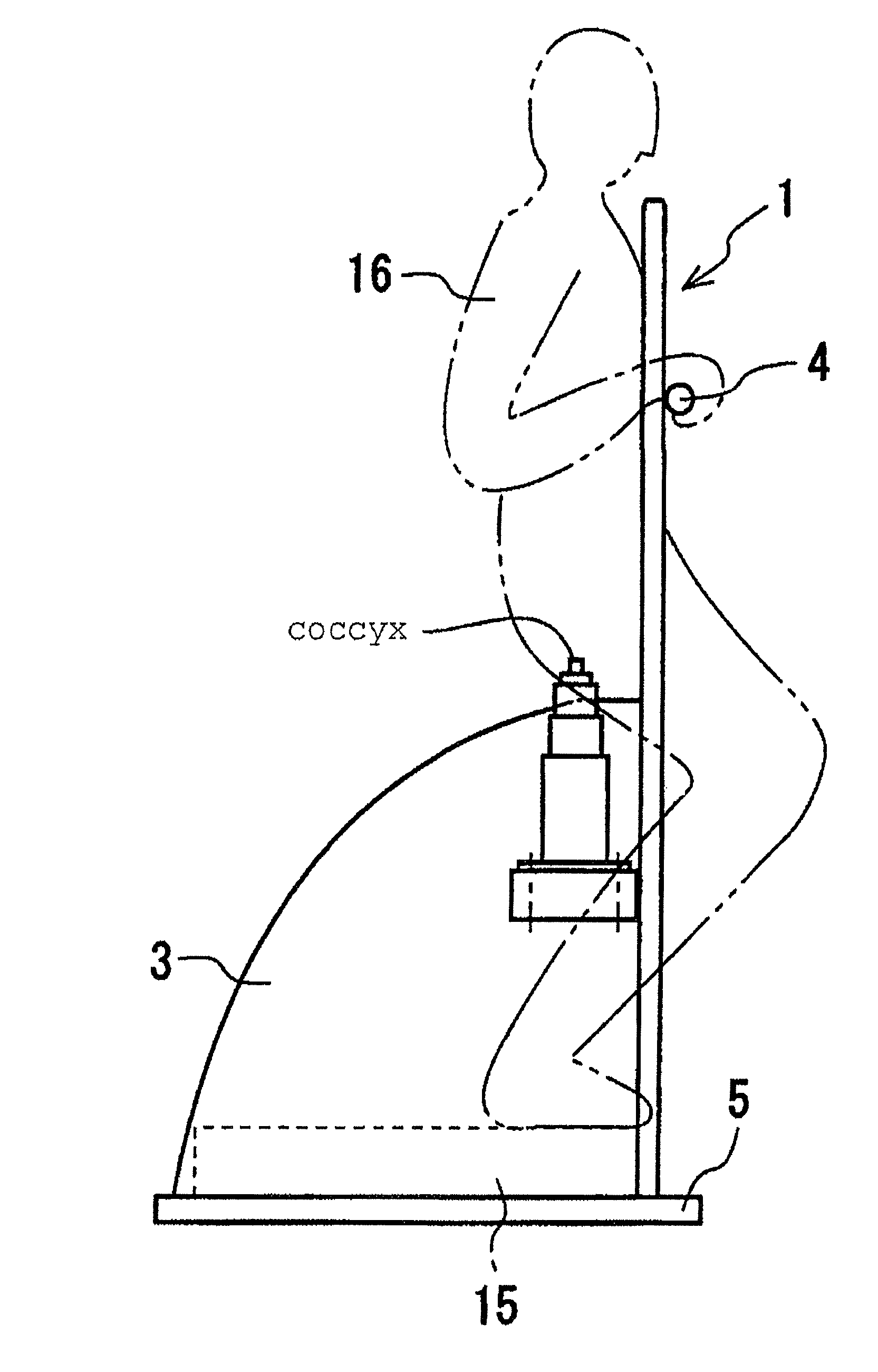
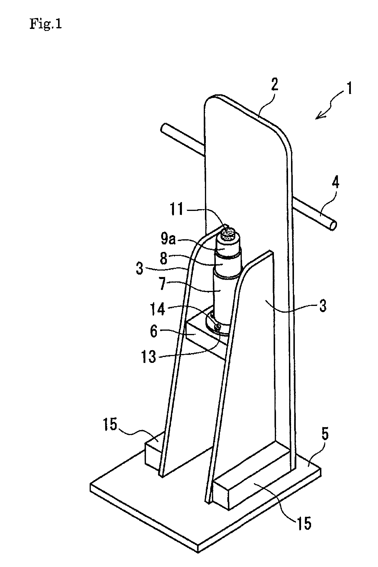
[0030]Embodiment 1 of the present invention will be described below with reference to FIGS. 1 and 2.

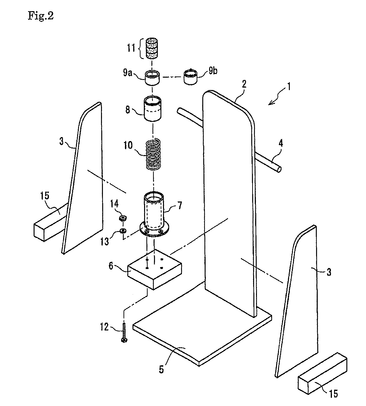
[0031]With a cylindrical casing 7 placed so that its axial direction is along the vertical direction, an inner cylindrical casing 8 and a coccyx contact treatment member 9a, each having a smaller diameter than that of the casing 7, are inserted thereinto. In this case, a coil spring as an elastic member 10 is provided below the inner cylindrical casing 8, and then the inner cylindrical casing 8 and the coccyx contact treatment member 9a are arranged so that they can slide vertically relative to the casing 7. With such an arrangement, the coccyx contact treatment member 9a is placed so that it can slide in the axial direction of the casing 7 through the elastic member 10.

[0032]The coccyx contact treatment member 9a has a cylindrical shape, is configured so that its diameter can be changed in accordance with the body size of a recipient, and has a flat surface to be contac...

embodiment 2

(Embodiment 2)

[0040]Embodiment 2 of the present invention will be described with reference to FIG. 3.

[0041]The internal configuration of a cylindrical casing 7 is the same as that in Embodiment 1.

[0042]In this embodiment, the cylindrical casing 7 is directly fixed to a base plate 5, which is a constituent element of a base, with bolts 12, washers 13, and nuts 14.

[0043]Longer longitudinal length of the cylindrical casing 7 reduces the number of components and allows simpler configuration as compared with Embodiment 1.

embodiment 3

(Embodiment 3)

[0044]Embodiment 3 of the present invention will be described with reference to FIG. 4.

[0045]The internal configuration of a cylindrical casing 7 is the same as that in Embodiment 1.

[0046]In this embodiment, a base for supporting a cylindrical casing 7 is constituted by a horizontal seat plate 6 and a base plate 5. The cylindrical casing 7 is fixed to the horizontal seat plate 6, which is a constitute element of the base, with bolts 12, washers 13, and nuts 14. The horizontal seat plate 6 is fixed to a posture holding member 2 with shelf supports 17, and the posture holding member 2 is fixed to the base plate 5 with bolts.

[0047]In this embodiment, it is only required to fix the horizontal seat plate 6 to the posture holding member 2, and therefore, as in the second embodiment, the number of components is smaller and simpler configuration is possible than in Embodiment 1.

[0048]The upper end faces of the cylindrical casing 7 and the coccyx contact treatment member 9a are...


PUM


Abstract

The invention provides a lumbago treatment instrument which manipulates the pelvis safely and properly by pressing the coccyx utilizing the patient's own body weight. A coccyx contact treatment member is disposed inside a cylindrical casing so as to be movable in the vertical direction via an elastic member. A coccyx contact buffering member made of sponge or the like is provided on the upper end of the coccyx contact treatment member. The patient straddles the coccyx contacting buffering member, assuming a sitting posture, and places the coccyx on the coccyx contact buffering member. In this posture, both feet are slightly lifted from the floor to apply the body weight on the coccyx contact buffering member so that the coccyx is pushed up from below. When doing so, the patient continues to maintain an upright posture while pressing the upper body against a posture holding member and gripping a handle with both hands.

Description

TECHNICAL FIELD[0001]The present invention relates to a low back pain treatment tool by means of correction of the sacrum, ilium, coccyx, or the like, or more specifically, by means of correction of the pelvis constituted thereby.BACKGROUND ART[0002]Pelvis correction is the most common method of relieving low back pain.[0003]As a conventional method for pelvis correction, there has been available a treatment method which uses a belt or traction device for fastening the pelvis. A temporary effect can be obtained by compressing only the pelvis using such a device, but the effect does not last very long: for example, the pain comes back after a predetermined period of time elapses since the end of the use of the belt or the like.[0004]Examples of such a device include the one that uses a geared motor (Patent Document 1) and the one that requires a recipient to perform light exercise (Patent Document 2). These devices should be used on a recipient who is in a sitting position, a supine ...

Claims


Application Information

Patent Timeline
Patent Type & Authority Patents(United States)
IPC IPC(8): A61H1/00A61F5/01
CPCA61H2205/081A61H2201/1664A61H2203/0431A61H2201/1623A61F5/01A61H2201/1635A61H2201/1284A61H1/006
Inventor TAGUCHI, HIROSHITAGUCHI, AKIKO
Owner TAGUCHI HIROSHI
Why Eureka
Try Eureka