Vertebral fixation system including torque mitigation

a technology of fixation system and vertebrae, which is applied in the field of various implantable medical devices, can solve the problems of reducing affecting the long-term stability of the installed elements, and affecting the safety of the nerve protected by the spin

Active Publication Date: 2014-12-30
ZIMMER BIOMET SPINE INC
View PDF46 Cites 38 Cited by
  • Summary
  • Abstract
  • Description
  • Claims
  • Application Information

AI Technical Summary

Benefits of technology

[0002]The present disclosure sets forth various implantable medical devices, and more pa...

Problems solved by technology

Back pain may be caused where one or more intervertebral discs degenerate resulting in pressure on the nerves protected by the spine.
For example, screws that are inserted int...

Method used


Image

  • Vertebral fixation system including torque mitigation
  • Vertebral fixation system including torque mitigation
  • Vertebral fixation system including torque mitigation

Examples


Embodiment Construction

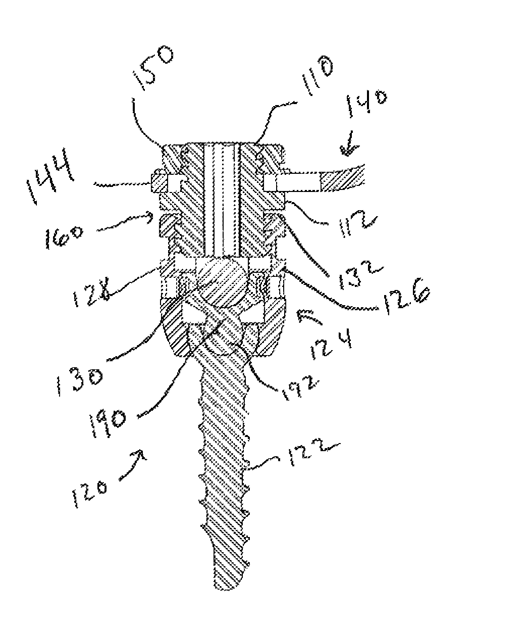
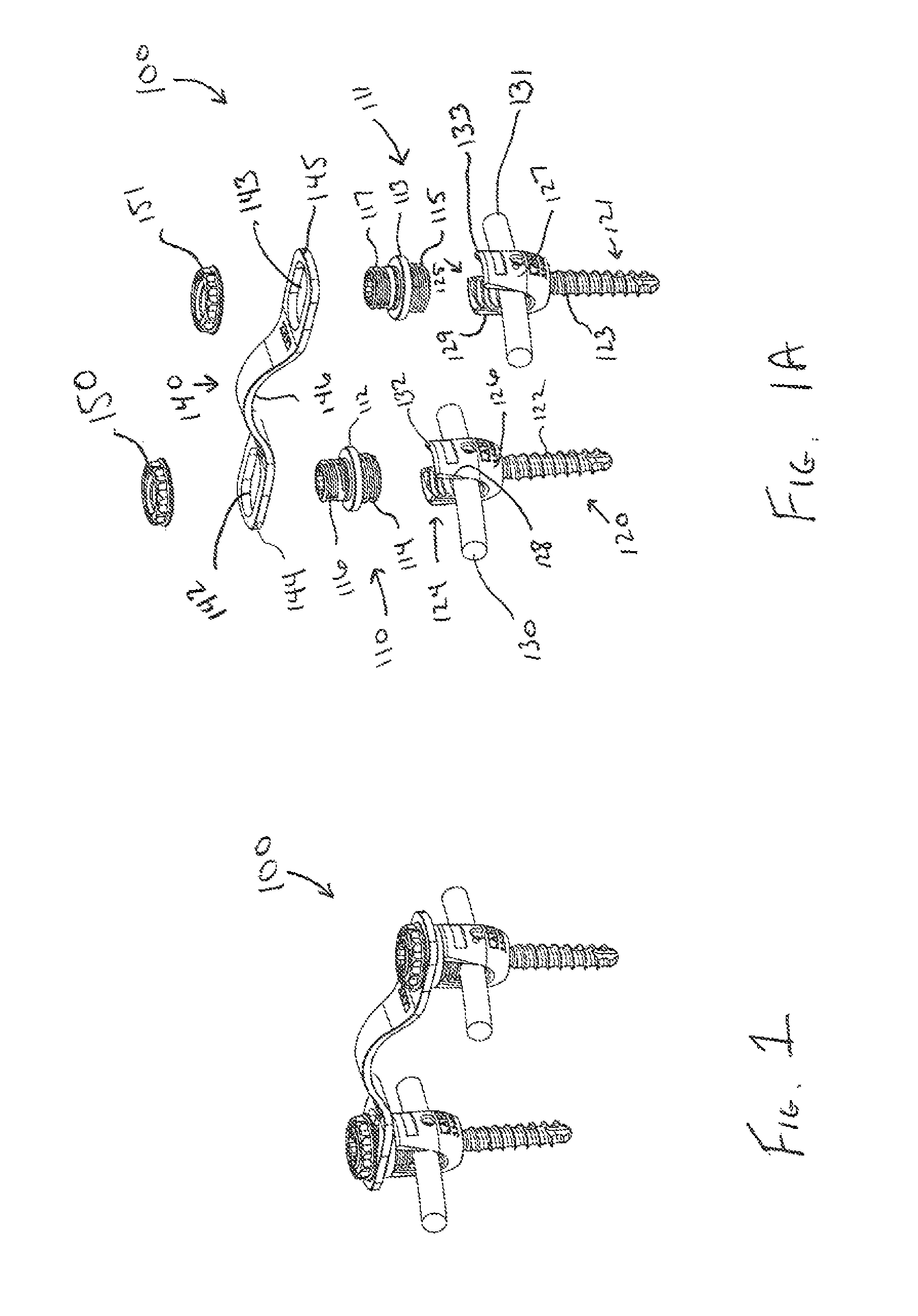
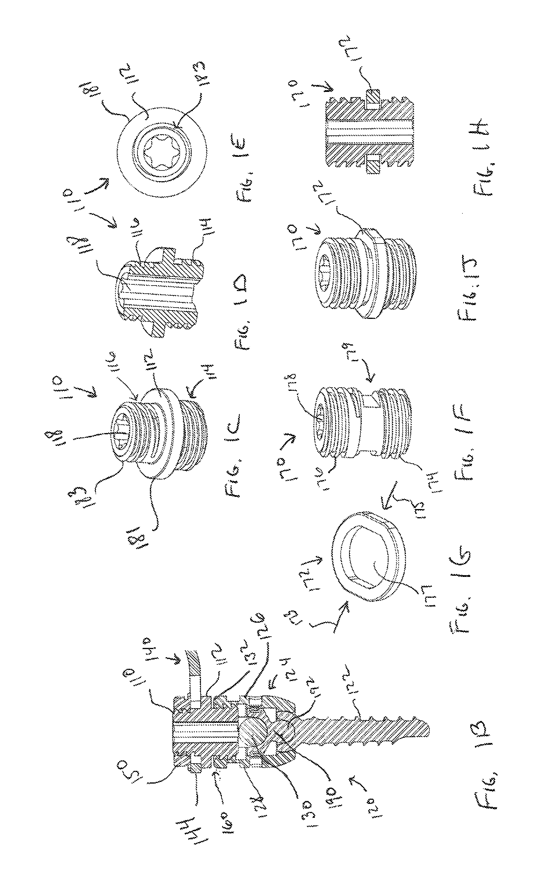
[0034]The present disclosure sets forth various implantable medical devices, and more particularly, various vertebral fixation systems and methods for using such are described herein.

[0035]Vertebral fixation systems may be used to fix one vertebra to another vertebra, as part of a spinal fusion or other surgical procedure. Vertebral fixation systems may include anchor devices that are installed into adjacent vertebrae. In some embodiments, the anchor devices are pedicle screws, and are used to anchor or couples rods which extend vertically across one or more disc segments. Depending on a variety of factors, including without limitation, the rod length and type, some fixation systems also include cross members which couple laterally between two rods or pedicle screws. In this manner, a single rod may be coupled to two or more anchor devices, and also may be coupled to a second rod. In some situations, the cross members cannot connect directly to rods. This may occur, for example, whe...


PUM


Abstract

Various spinal fixation assemblies are presented that include a separator installable in relation to a coupler attached to the head of an anchor device, and disposable between the head of the anchor device and a cross member. The separators may be implemented in a variety of forms.

Description

RELATED APPLICATIONS[0001]The present application claims priority from U.S. Provisional Patent Application No. 61 / 430,875 entitled “Vertebral Fixation System Including Torque Mitigation” by: Ziemek et al., filed on Jan. 7, 2011, which Provisional Patent Application is hereby incorporated by reference in its entirety.BACKGROUND[0002]The present disclosure sets forth various implantable medical devices, and more particularly, various vertebral fixation systems and methods for using such are described herein.[0003]Back pain may be caused where one or more intervertebral discs degenerate resulting in pressure on the nerves protected by the spine. In some cases, to relieve pressure on the nerves, vertebrae on either side of a problem intervertebral disc are fused together. Fusing the vertebrae typically includes fixing the opposing vertebrae such that the fixed vertebrae cannot move relative to one another. By fixing the vertebrae relative to each other, the region between the vertebrae ...

Claims


Application Information

Patent Timeline
IPC IPC(8): A61B17/70
CPCA61B17/7052A61B17/70
Inventor ZIEMEK, TERRYCAUSEY, GREGFULTON, MICHAEL
Owner ZIMMER BIOMET SPINE INC
Why Eureka
Try Eureka