Internal metal support structure for mobile device

a metal support and mobile device technology, applied in the direction of electrical apparatus casings/cabinets/drawers, instruments, computing, etc., can solve the problems that the best combination of weight, rigidity and strength of materials such as metals and carbon fibers may have detrimental effects on transmitted or received radio signals

Active Publication Date: 2014-12-30
AMAZON TECH INC
View PDF61 Cites 18 Cited by
  • Summary
  • Abstract
  • Description
  • Claims
  • Application Information

AI Technical Summary

Problems solved by technology

However, materials such as metals and carbon fibers that provide the best combination of weigh

Method used


Image

  • Internal metal support structure for mobile device
  • Internal metal support structure for mobile device
  • Internal metal support structure for mobile device

Examples


Embodiment Construction

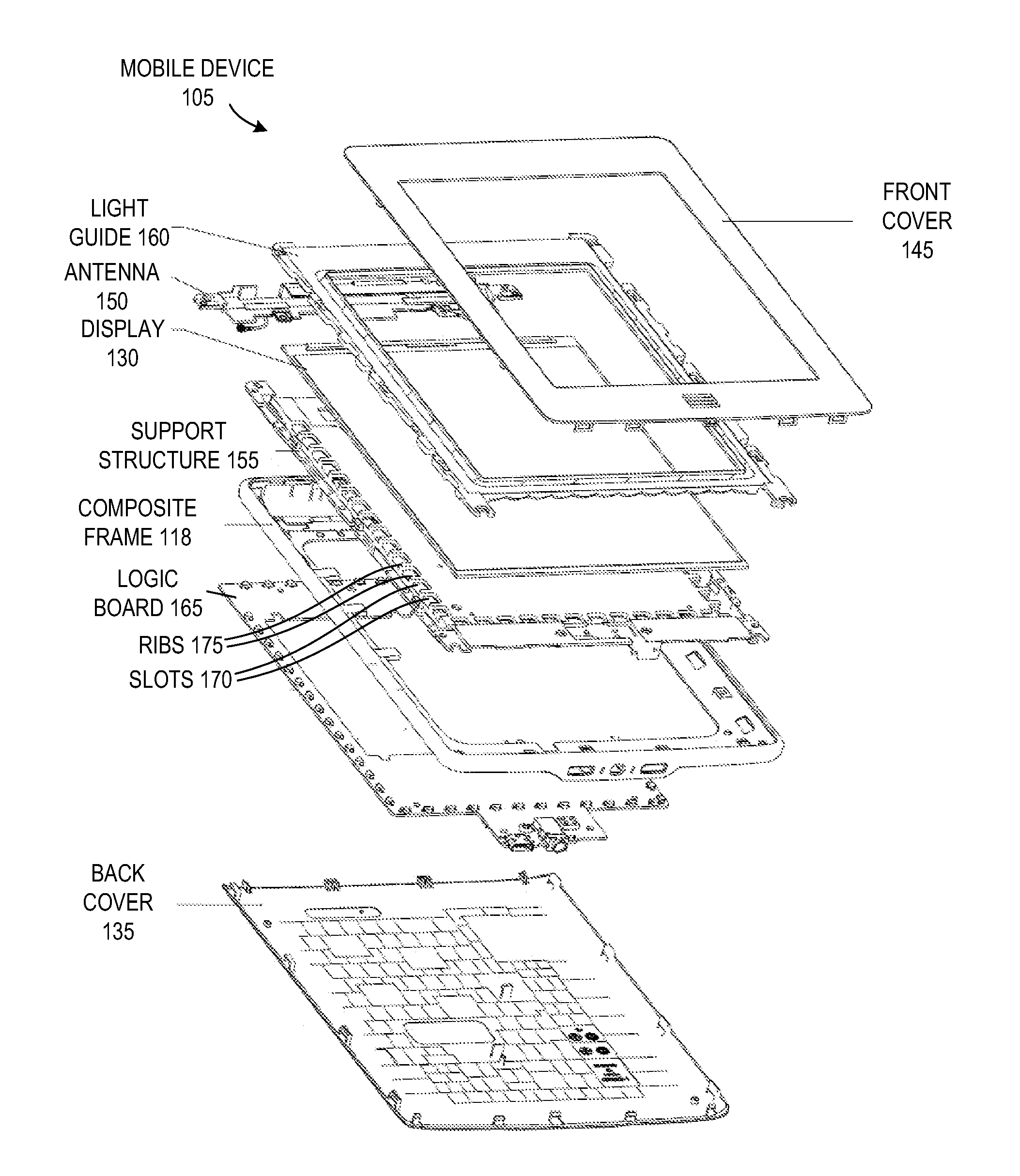
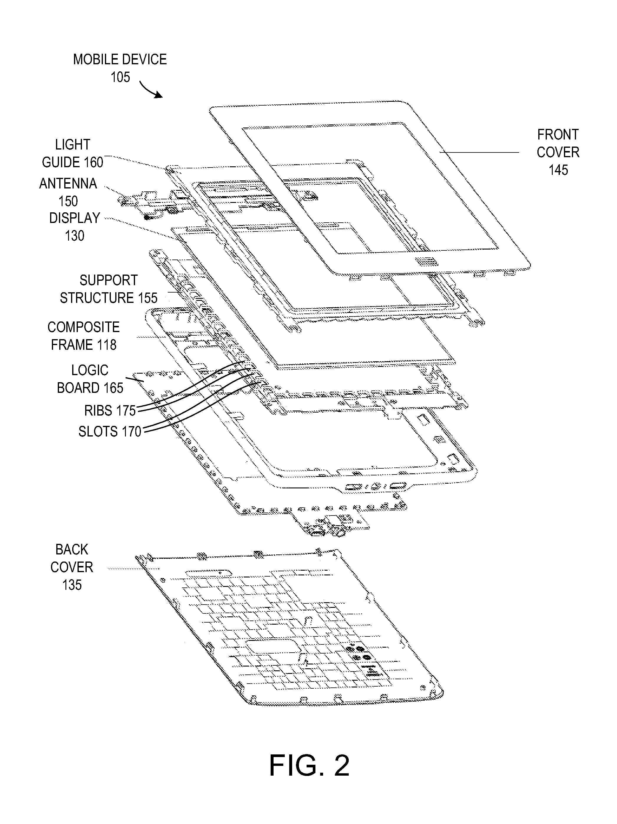
[0018]Structures for use in mobile electronic devices (also referred to herein simply as mobile devices) and processes for manufacturing such structures are described herein. The mobile devices may be any content rendering devices that include a wireless modem for connecting the mobile devices to a wireless network. Examples of such mobile devices include electronic book readers, cellular telephones, personal digital assistants (PDAs), portable media players, tablet computers, netbooks, and the like.

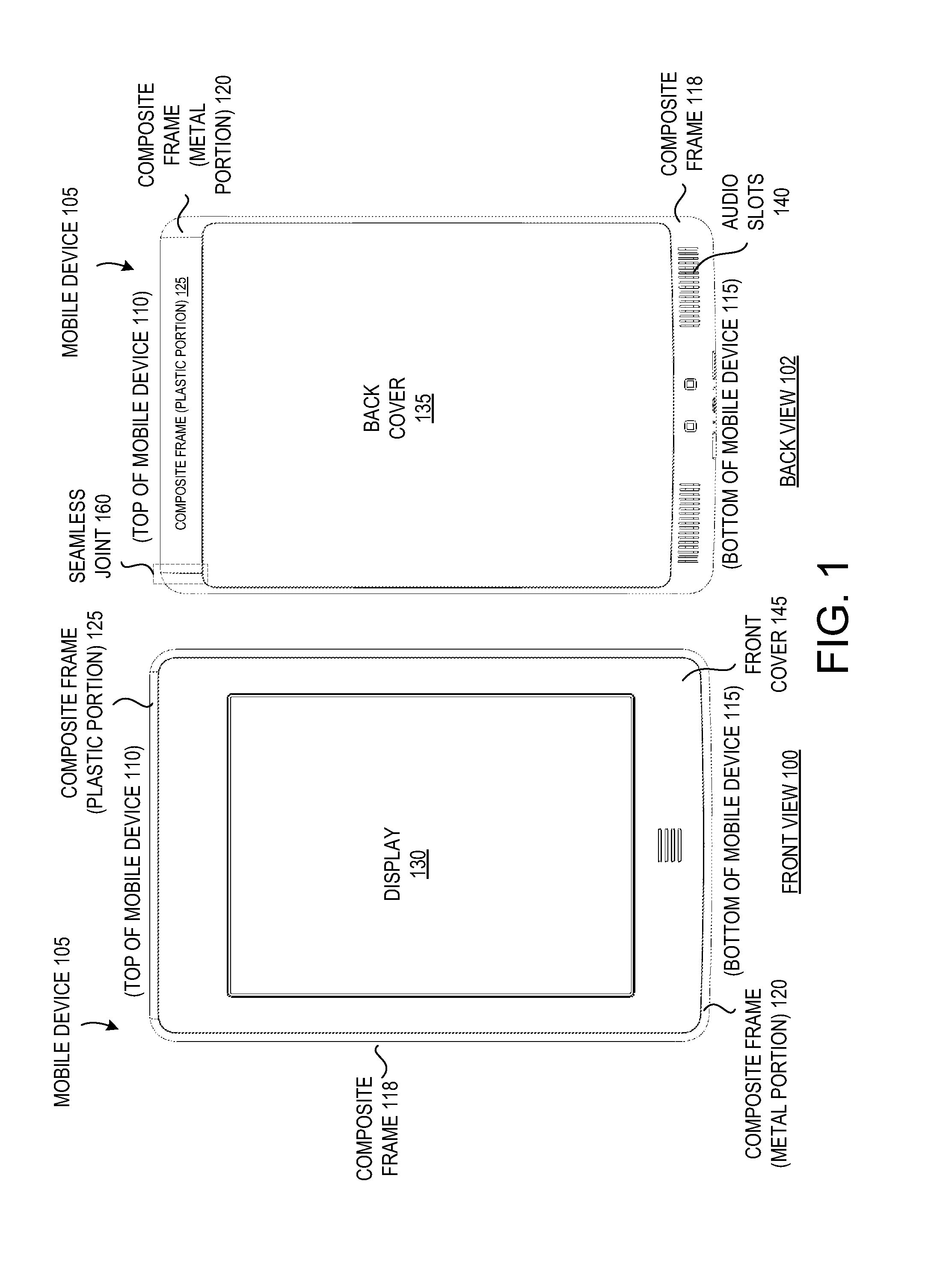
[0019]In one embodiment, a mobile device includes a composite frame that includes both metal and plastic. The composite frame may include a metal region having multiple sides and a hollow center. At least one side of the metal region has multiple voids. The metal region may be formed by metal die casting. The composite frame further includes a plastic region composed of glass impregnated plastic. The plastic region is mechanically bonded to the metal region. The bond is achieved via prot...


PUM


Abstract

A metal support structure for a mobile device includes a substantially flat front side configured to support a display and a back side having a lattice structure configured to provide rigidity to the mobile device while keeping a weight below a weight threshold, and to support a logic board. The metal support structure further includes a plurality of slots around a periphery of the metal support structure, configured to permit emitters for an infrared touch sensor mounted on the logic board to project infrared beams to receivers mounted on the logic board.

Description

RELATED APPLICATIONS[0001]This application is related to co-pending U.S. patent application Ser. No. 13 / 431,820 filed Mar. 27, 2012, which is assigned to the assignee of the present application.BACKGROUND OF THE INVENTION[0002]The use of mobile electronic devices has become pervasive in society. It is often desirable for such mobile electronic devices to be as light as possible while retaining beneficial structural properties such as high rigidity and material strength. However, materials such as metals and carbon fibers that provide the best combination of weight, rigidity and strength may have detrimental effects to transmitted or received radio signals.BRIEF DESCRIPTION OF THE DRAWINGS[0003]The embodiments described herein will be understood more fully from the detailed description given below and from the accompanying drawings, which, however, should not be taken to limit the application to the specific embodiments, but are for explanation and understanding only.[0004]FIG. 1 ill...

Claims


Application Information

Patent Timeline
IPC IPC(8): G06F1/16
CPCG06F1/1656
Inventor OWEN, STEVEN L.ASUNCION, BRYAN C.
Owner AMAZON TECH INC
Why Eureka
Try Eureka