
Cognitive WiFi radio network

a radio network and wifi technology, applied in the field of wireless networks, can solve the problems of inability to adapt to wide-area networks, inability to use wide-area networks, and inability to meet the needs of users, so as to avoid radio interference in the wifi network, the effect of avoiding interferen

Inactive Publication Date: 2014-12-30
HER MAJESTY THE QUEEN & RIGHT OF CANADA REPRESENTED BY THE MIN OF IND THROUGH THE COMM RES CENT
View PDF8 Cites 15 Cited by
  • Summary
  • Abstract
  • Description
  • Claims
  • Application Information

AI Technical Summary

Problems solved by technology

This makes them attractive for delivering ‘last mile’ voice and data services from a fiber backbone to end users in rural area with low population density, or generally in areas where existing alternatives for the ‘last mile’ service delivery, such as WIMAX, land-line phone networks, TV cable and optical fiber based solutions, are too expensive or unfeasible for other reasons.
However, conventional WiFi networks are limited to relatively compact environments, such as homes and small offices, and are not suitable for wide-area networks where spectrum may be re-used in different sectors of a base transceiver station (BTS) site.
Collision avoidance is used to improve CSMA performance by not allowing wireless transmission of a terminal if another terminal is transmitting, thus reducing the probability of collision due to the use of a random truncated binary exponential backoff time.
However, when a WiFi network includes multiple access points (APs) each providing wireless access to a plurality of client terminals, same WiFi channels may be used by different APs in overlapping areas, the conventional WiFi MAC becomes inefficient, and the transmission in all sectors must be synchronized.
One drawback of the WiFiRe system is its insufficient resilience to ISM band interference, as the loss of either of the UL-MAP or the DL-MAP messages would severely affect the uplink and downlink scheduling, causing a multiplicity of errors that may last for a period of time longer than the actual interference event.

Method used


Image

  • Cognitive WiFi radio network
  • Cognitive WiFi radio network
  • Cognitive WiFi radio network

Examples


Embodiment Construction

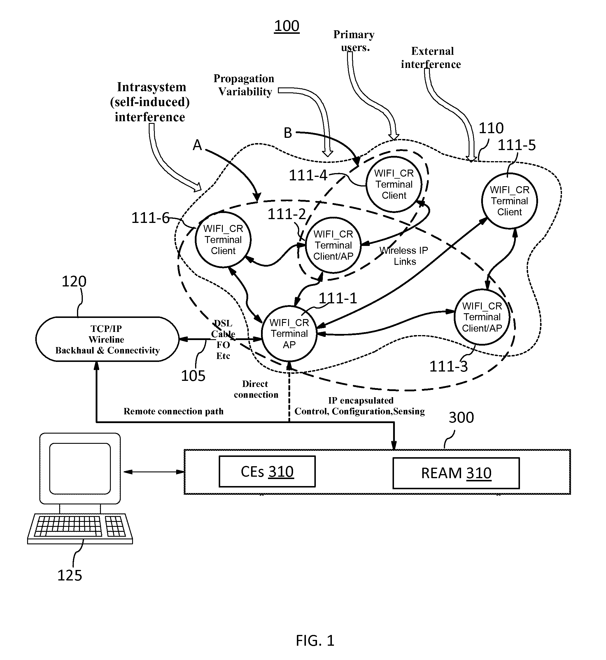
[0025]The invention will be described in connection with a number of exemplary embodiments. To facilitate an understanding of the invention, many aspects of the invention are described in terms of sequences of actions to be performed by functional elements of a CR WiFi network system, including but not limited to WiFi_CR terminals. It will be recognized that in each of the embodiments, the various actions including those depicted as blocks in flow-chart illustrations and block schemes could be performed by specialized circuits, for example discrete logic gates interconnected to perform a specialized function, by computer program instructions being executed by one or more processors, or by a combination of both. Thus, the various aspects of the invention may be embodied in many different forms, and all such forms are contemplated to be within the scope of the invention.

[0026]As used herein, the terms “first”, “second” and so forth are not intended to imply sequential ordering, but ra...


PUM


Abstract

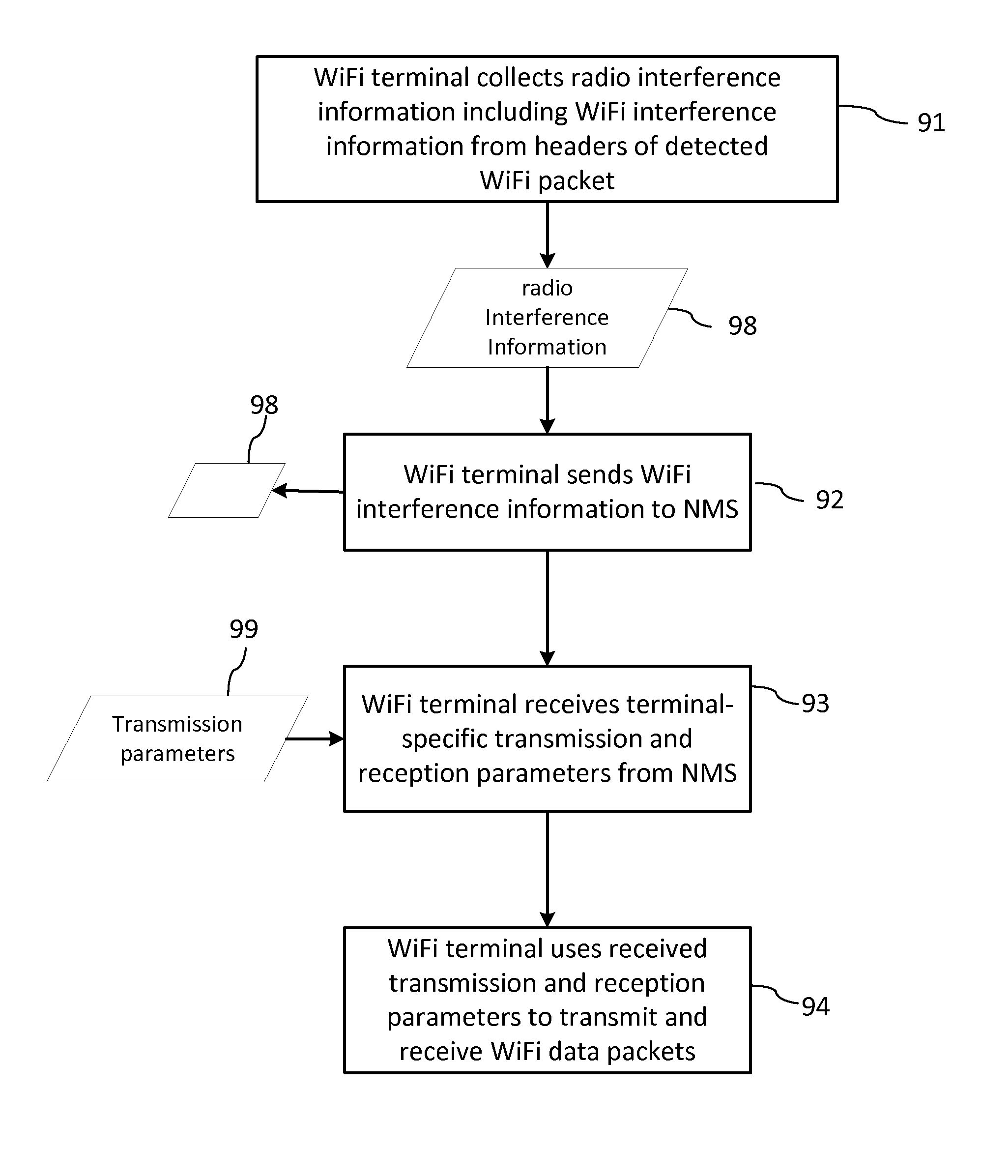
The invention relates to a cognitive radio (CR) WiFi network which includes a plurality of radio environment aware WiFi terminals, which collect local WiFi interference information and send this information to a CR network management system (NMS). The CR NMS includes a database for storing historical records of the interference information obtained from the terminals, and cognitive engines for analyzing the stored historical interference records and determining terminal-specific transmission and reception parameters. In one embodiment the network implements a deterministic NMS-directed networks-wide TDD / TDM scheduling of WiFi communications for optimal channel re-use and interference avoidance, and a novel terminal synchronization mechanism.

Description

CROSS-REFERENCE TO RELATED APPLICATIONS[0001]The present invention claims priority from U.S. Provisional Patent Application No. 61 / 471,982 filed Apr. 5, 2011, which is incorporated herein by reference.TECHNICAL FIELD[0002]The present invention generally relates to wireless networks and devices used therein, and more particularly relates to WiFi-type radio networks utilizing distributed interference sensing and interference avoidance.BACKGROUND OF THE INVENTION[0003]The proliferation of WiFi networks based on the IEEE 802.11 wireless RLAN (radio local area network) standard, commercially known as WiFi®, Wi-Fi or WIFI, had led to availability of inexpensive WiFi devices and chipsets implementing various aspects of the IEEE 802.11 standards. This makes them attractive for delivering ‘last mile’ voice and data services from a fiber backbone to end users in rural area with low population density, or generally in areas where existing alternatives for the ‘last mile’ service delivery, such...

Claims


Application Information

Patent Timeline
Patent Type & Authority Patents(United States)
IPC IPC(8): H04W84/12H04W16/14H04W72/08H04W4/00
CPCH04W72/082H04W84/12H04W16/14H04W72/541
Inventor SYDOR, JOHNROBERTSDORAY, BERNARDPALANINATHAN, SIVABRETT, WAYNEBENNAI, MUSTAPHA
Owner HER MAJESTY THE QUEEN & RIGHT OF CANADA REPRESENTED BY THE MIN OF IND THROUGH THE COMM RES CENT
Learn More