Eureka AIR delivers breakthrough ideas for toughest innovation challenges, trusted by R&D personnel around the world.

Dynamic building of monitored set

a dynamic building and set technology, applied in the field of wireless telecommunications, can solve problems such as the inability to configure this information statically

Active Publication Date: 2009-11-03
TELEFON AB LM ERICSSON (PUBL)
View PDF63 Cites 143 Cited by
  • Summary
  • Abstract
  • Description
  • Claims
  • Application Information

AI Technical Summary

Problems solved by technology

Problems occur when attempting to perform handover from the macro network (i.e. macrocells) to the femto cells.
One significant problem in the handover procedure involves defining or knowing the femto cells in the Neighboring Cell Lists in the macro network.
Furthermore, it is not feasible to configure this information statically as the end users are able to move the home RBS on their own to a new location.
Another problem occurs in providing Access Control for end user involved in Handover from the macro network to femto cells.

Method used


Image

  • Dynamic building of monitored set
  • Dynamic building of monitored set
  • Dynamic building of monitored set

Examples


Embodiment Construction

[0035]In the following description, for purposes of explanation and not limitation, specific details are set forth such as particular architectures, interfaces, techniques, etc. in order to provide a thorough understanding of the present invention. However, it will be apparent to those skilled in the art that the present invention may be practiced in other embodiments that depart from these specific details. That is, those skilled in the art will be able to devise various arrangements which, although not explicitly described or shown herein, embody the principles of the invention and are included within its spirit and scope. In some instances, detailed descriptions of well-known devices, circuits, and methods are omitted so as not to obscure the description of the present invention with unnecessary detail. All statements herein reciting principles, aspects, and embodiments of the invention, as well as specific examples thereof, are intended to encompass both structural and functiona...


PUM


Abstract

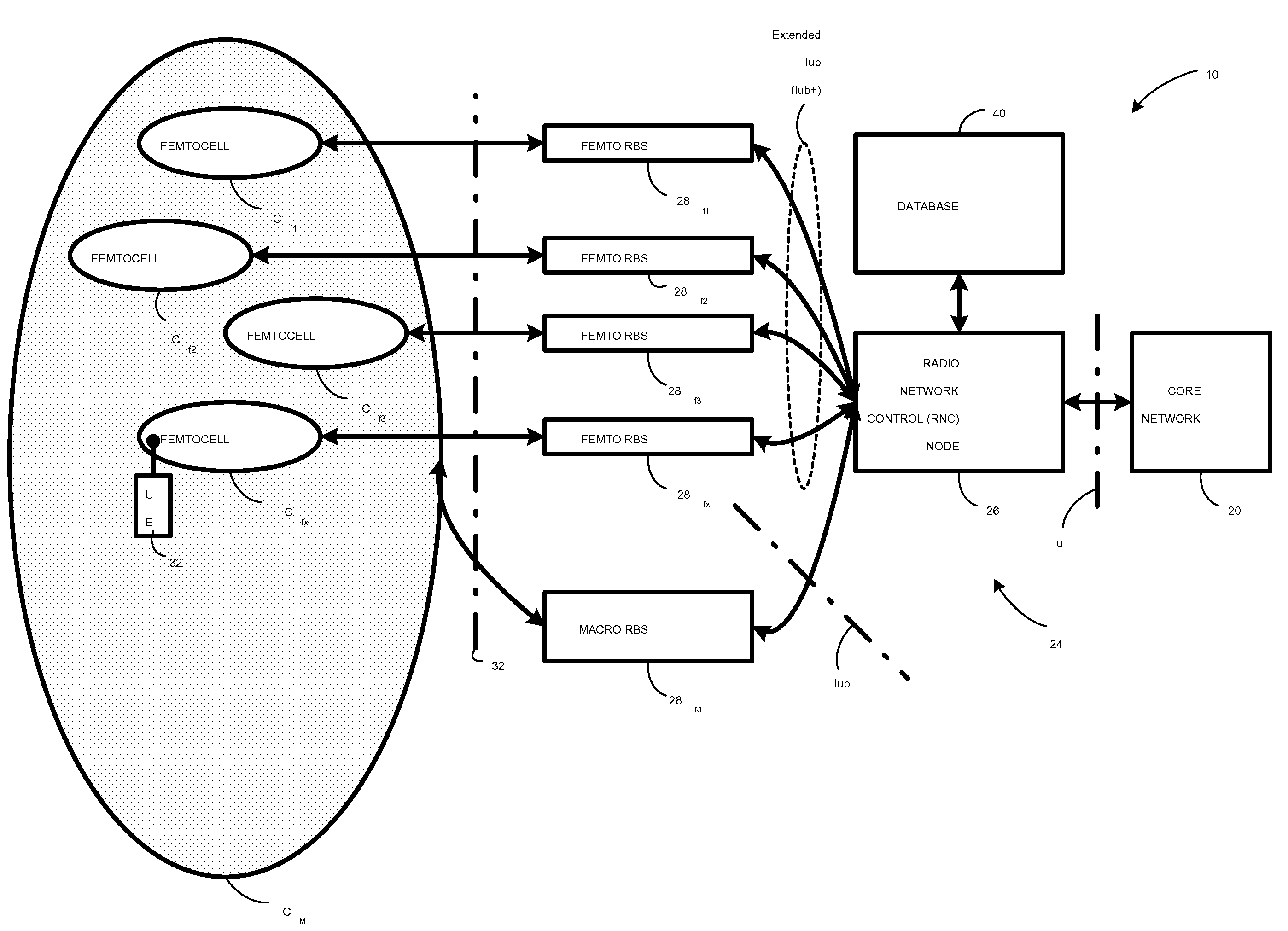
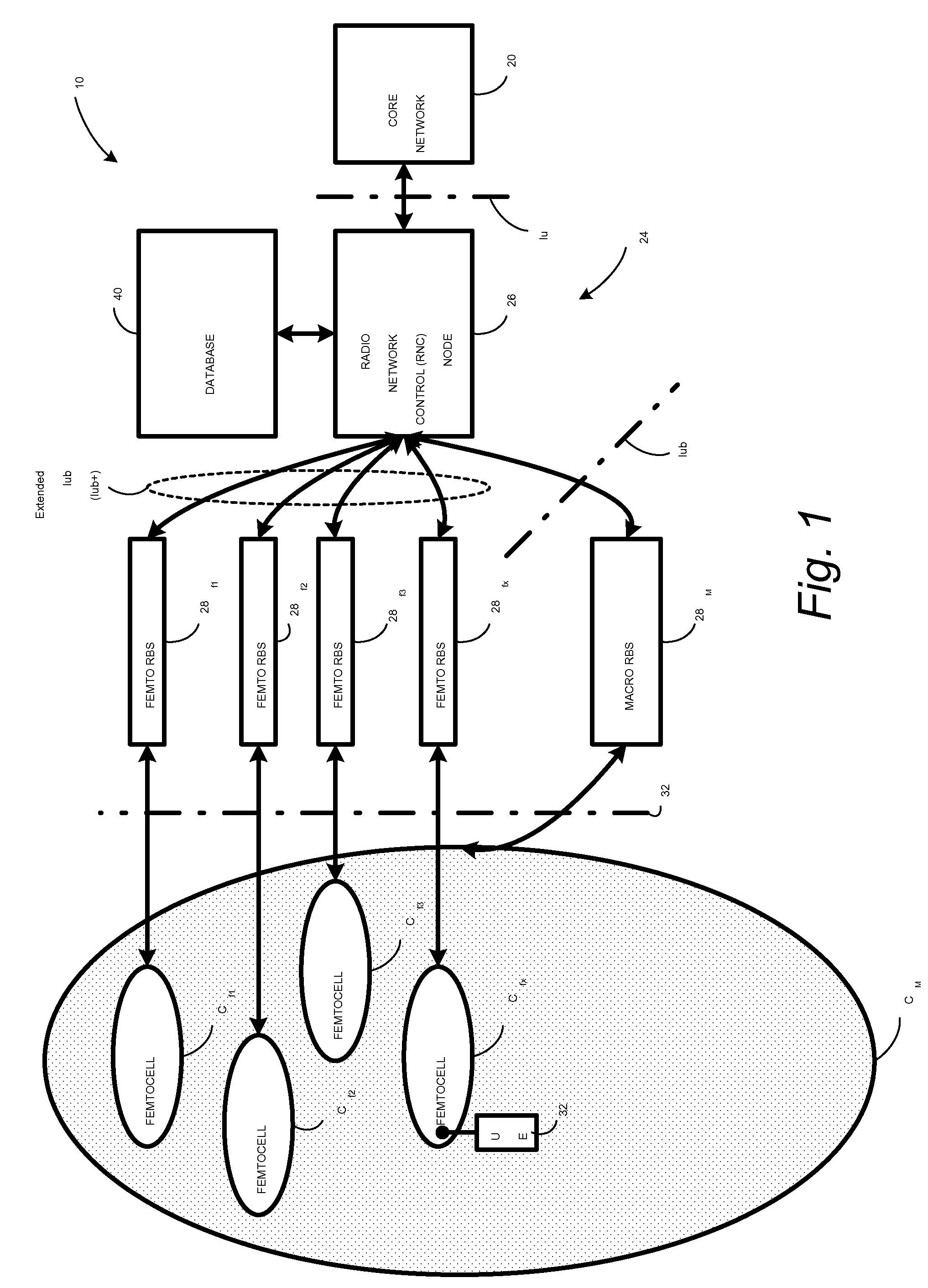
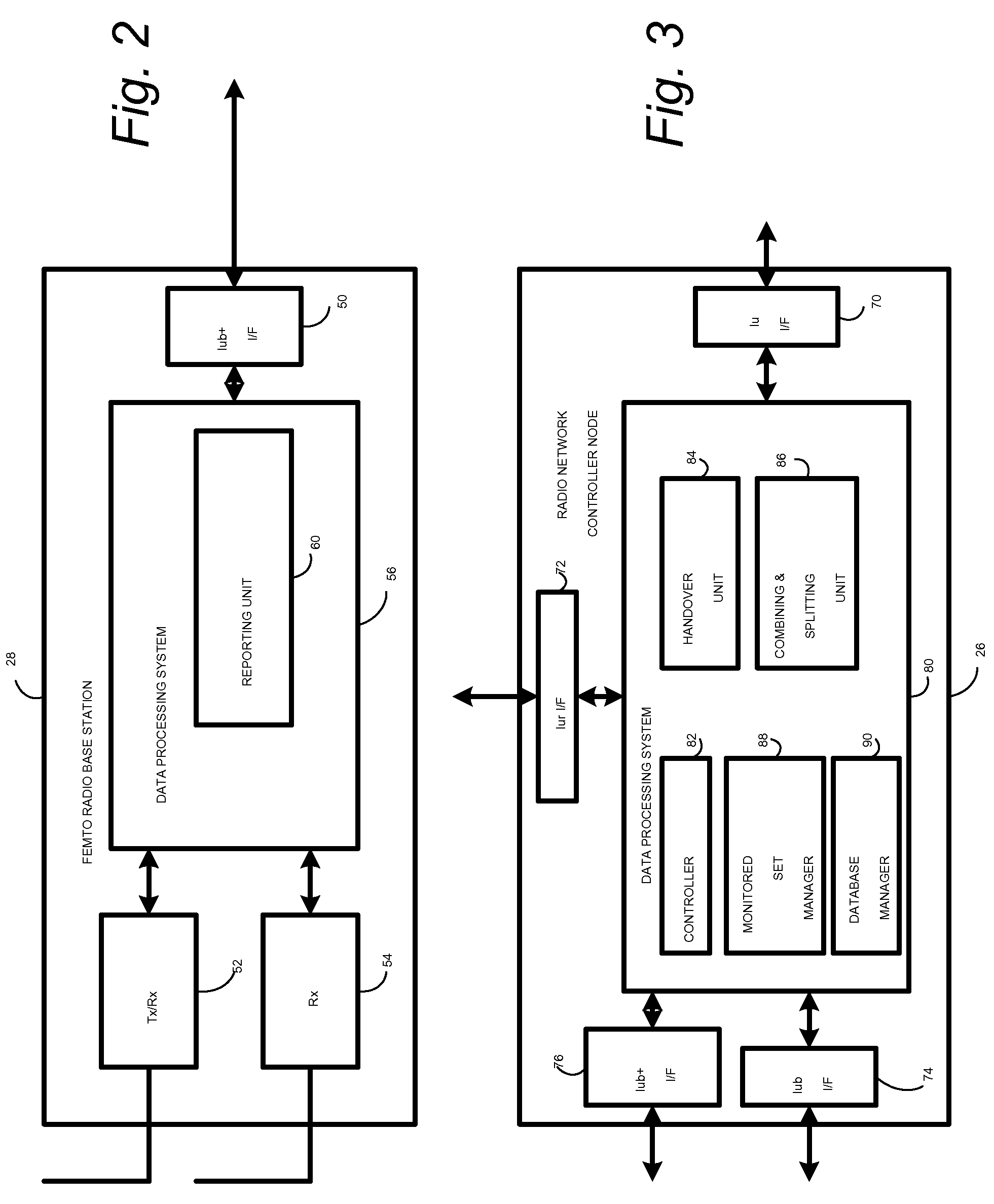
A radio access network (24) comprises a radio network control node (26); a database (40); and a femto radio base station node (28f) serving a femtocell (Cf) of the radio access network. The femto radio base station node (28f) comprises a receiver (54) for receiving scanned cell information broadcast for one or more receivable cells of the radio access network, and a reporting unit (60). The reporting unit (60) provides the scanned cell information for the one or more receivable cells of the radio access network to the radio network control node (26). The radio network control node (60) is arranged, upon receipt of the scanned cell information, for providing configuration information to the femto radio base station node (for configuring the femto radio base station node) and for storing macro cell information for one or more receivable cells in the database (40). The macrocell information is stored in the database (40) in association with the femto radio base station node.

Description

BACKGROUND[0001]I. Technical Field[0002]This invention pertains to wireless telecommunications, and particularly to construction and / or maintenance of a monitored set of cells for a mobile station.[0003]II. Related Art and Other Considerations[0004]In a typical cellular radio system, wireless user equipment units (UEs) communicate via a radio access network (RAN) to one or more core networks. The user equipment units (UEs) can be mobile stations such as mobile telephones (“cellular” telephones) and laptops with mobile termination, and thus can be, for example, portable, pocket, hand-held, computer-included, or car-mounted mobile devices which communicate voice and / or data with radio access network. Alternatively, the wireless user equipment units can be fixed wireless devices, e.g., fixed cellular devices / terminals which are part of a wireless local loop or the like.[0005]The radio access network (RAN) covers a geographical area which is divided into cell areas, with each cell area ...

Claims


Application Information

Patent Timeline
Patent Type & Authority Patents(United States)
IPC IPC(8): H04M11/00H04W36/04H04W48/12H04W48/16H04W92/12
CPCH04W36/04H04W48/12H04W48/16H04W84/045H04W92/12
Inventor LINDQVIST, THOMAS LARS ERIKNYLANDER, TOMASVIKBERG, JARI TAPIO
Owner TELEFON AB LM ERICSSON (PUBL)
Why Eureka
Eureka Blog
Learn More