Flat panel display remote-controlled viewing angle adjustment system

a technology of remote control and viewing angle, which is applied in the direction of television systems, electrical apparatus casings/cabinets/drawers, instruments, etc., can solve the problems of structural weakness of the support device, too weak structure of the support device formed of links or arms, etc., and achieve the effect of overcompensating the structural weakness

Active Publication Date: 2015-01-27
FANG JIN +1
View PDF3 Cites 3 Cited by
  • Summary
  • Abstract
  • Description
  • Claims
  • Application Information

AI Technical Summary

Benefits of technology

[0008]One object of the present invention is to provide a flat panel display remote-controlled viewing angle adjustment system that can overcome the weakness in the structure inherent to most support devices for flat panel displays in which links or arms are used.
[0009]Another object of the present invention is to provide a flat panel display remote-controlled viewing angle adjustment system that is motor driven such that the flat panel display remote-controlled viewing angle adjustment system can be operated automatically.
[0010]Another object of the present invention is to provide a flat panel display remote-controlled viewing angle adjustment system which is remotely controlled such that a user can easily adjust the viewing angle of the flat display panel.

Problems solved by technology

Furthermore, as the display panel gets larger and heavier, the structure of a support device formed of links or arms can be too weak to safely support it.
Furthermore, when the angle of a display is adjusted, the center of gravity of the device as disclosed above will be displaced away from the wall or the surface where the device / display is mounted, and the displacement will impose additional stress on the support device, especially in translational movement, further aggravating the problem of structural weakness of the support device.

Method used


Image

  • Flat panel display remote-controlled viewing angle adjustment system
  • Flat panel display remote-controlled viewing angle adjustment system
  • Flat panel display remote-controlled viewing angle adjustment system

Examples


first embodiment

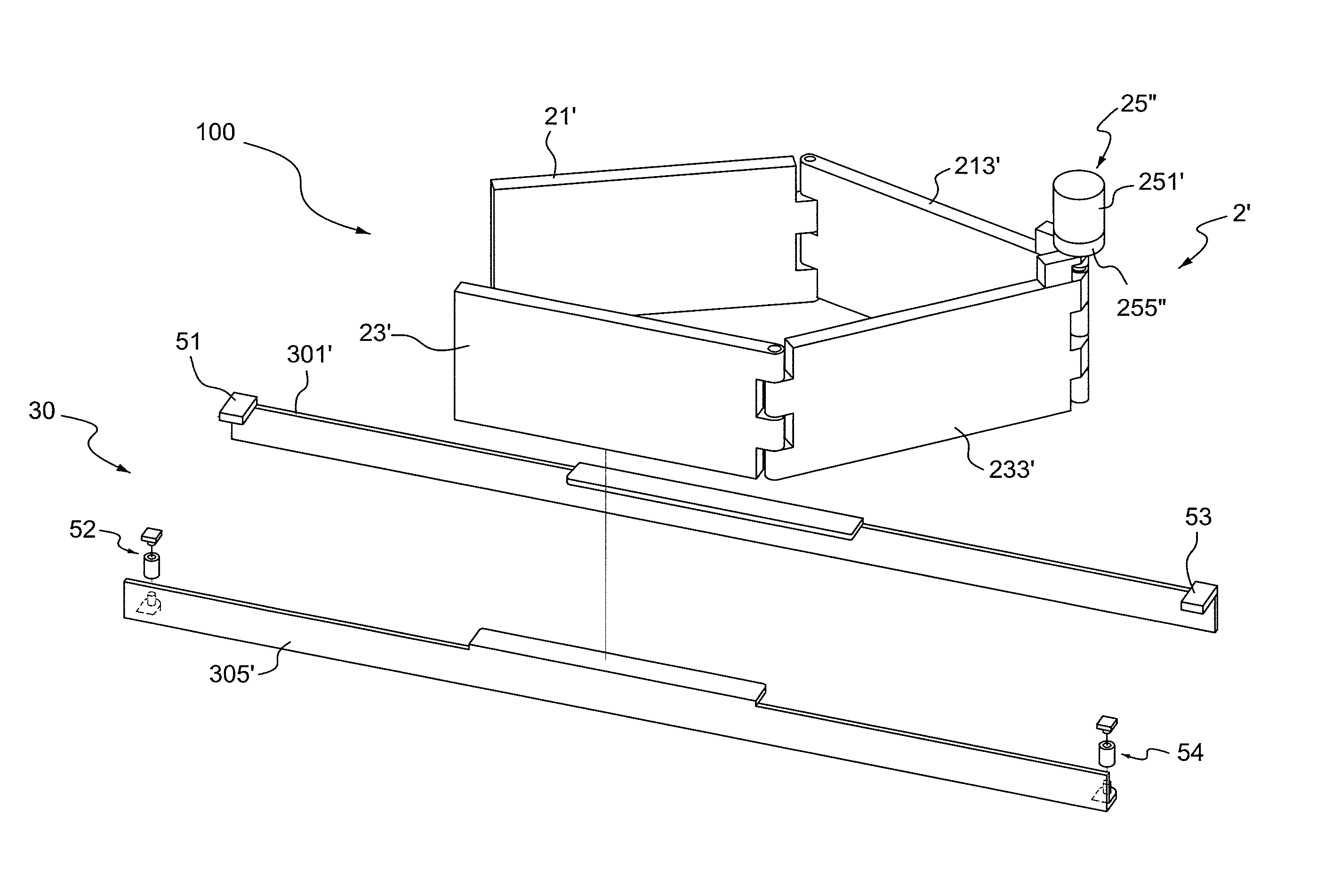
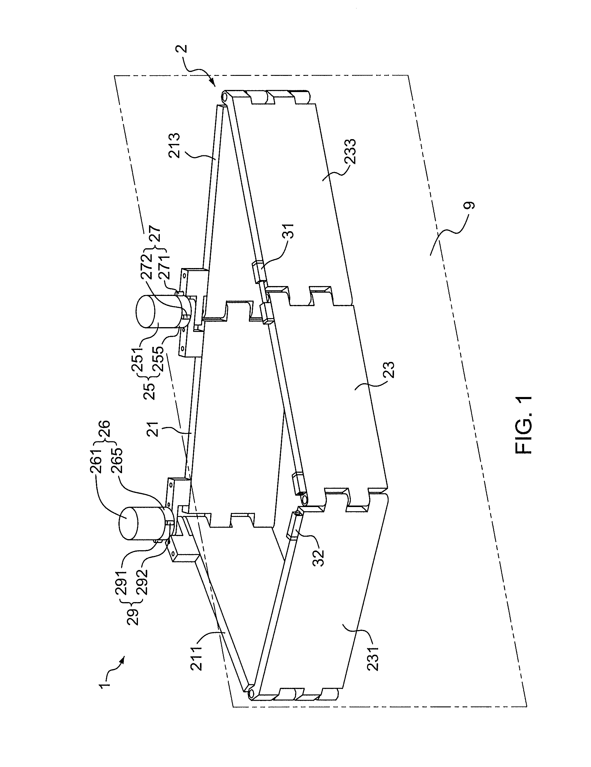
[0032]FIG. 1 and FIGS. 2A-2D show the flat panel display remote-controlled viewing angle adjustment system 1. The system 1 comprises a support assembly 2, which further comprises a base support panel member 21, a display support panel member 23, a first support panel member 233, a second support panel member 213, a third support panel member 231, and a fourth support panel member 211. The base support panel member 21 can be fixed to a support or on a wall and the display support panel member 23 is to support a flat panel display 9. The right edge of the base support panel member 21 is pivotally connected to the left edge of the second support panel member 213 and the left edge of the base support panel member 21 is pivotally connected to the right edge of the fourth support panel member 211. The right edge of the display support panel member 23 is pivotally connected to the left edge of the first support panel member 233 and the left edge of the display support panel member 23 is pi...

second embodiment

[0046]FIG. 4 shows the flat panel display remote-controlled viewing angle adjustment system 1. The system 1 comprises a support assembly 2, which further comprises a base support panel member 21, a display support panel member 23, a first support panel member 233, a second support panel member 213, a third support panel member 231, and a fourth support panel member 211. The base support panel member 21 can be fixed to a support or on a wall and the display support panel member 23 is to support a flat panel display 9. The right edge of the base support panel member 21 is pivotally connected to the left edge of the second support panel member 213 and the left edge of the base support panel member 21 is pivotally connected to the right edge of the fourth support panel member 211. The right edge of the display support panel member 23 is pivotally connected to the left edge of the first support panel member 233 and the left edge of the display support panel member 23 is pivotally connect...

third embodiment

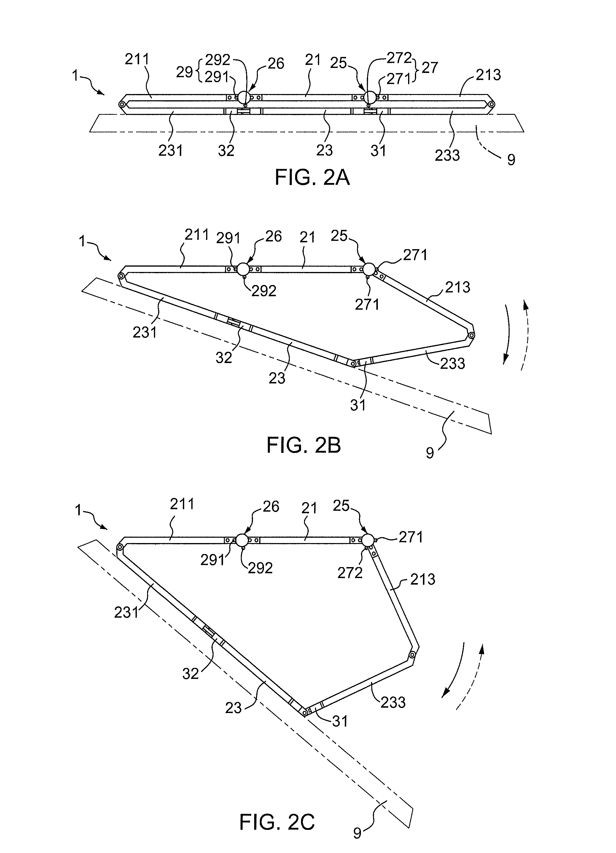
[0061]FIGS. 8A-8D show an operating process of the present invention. As shown in FIG. 8A, when the flat panel display remote-controlled viewing angle adjustment system 10 is at the initial position, the base support panel member 21, the second support panel member 213, and the fourth support panel member 211 form one plane, and the display support panel member 23, the first support panel member 233, and the third support panel member 231 form another plane parallel to and directly in front of the former plane. At this position, the first positioning switch 271 and second positioning switch 291 are in the “on” mode, and the first limit switch 272 and the second limit switch 292 are in the “off” mode. As shown in FIGS. 8B and 8C, when the first driving mechanism 25 is started, the motor 251 will drive the second support panel member 213 to rotate clockwise about the pivot joint of the second support panel member 213 and the base support panel member 21. The first positioning switch 2...


PUM


Abstract

A flat panel display remote-controlled viewing angle adjustment system (1) comprising a support assembly (2) for supporting a flat panel display (9), an electrical driving assembly for driving the support assembly (2), and an angular control assembly attached to the support assembly (2). The adjustable system (1) is configured such that when the electrical driving assembly is started, the flat panel display (9) is rotated about a vertical axis that passes through one of the left side and the right side of the flat panel display (9) and only when the flat panel display (9) returns to zero angle position can it rotate about a vertical axis that passes through the other of the left side and the right side of the flat panel display (9).

Description

TECHNICAL FIELD[0001]The present invention generally relates to a flat panel display remote-controlled viewing angle adjustment system, and more particularly to such a device for which the viewing angle of the flat panel display can be remotely adjusted.BACKGROUND OF INVENTION[0002]Flat panel displays, such as LCD and plasma television, have become increasingly popular and now almost dominate the market which used to belong to traditional CRT. Because flat panel displays are thin in profile, they are often mounted on walls, brackets, or other vertical flat surfaces in order to save space. For a better viewing angle, flat panel displays are often mounted on a support device which can be rotated to a desired angle. Numerous patents directed to mounting devices allow the viewing angle to be adjusted can be found.[0003]U.S. Pat. No. 7,296,774 (Sung I. Oh) is directed to a viewing angle adjustment system, which provides a support arm to couple a monitor to a surface such as a wall or cei...

Claims


Application Information

Patent Timeline
Patent Type & Authority Patents(United States)
IPC IPC(8): H05K5/00H04N7/14A47G29/00H05K7/00H04N5/14F16M11/08F16M11/18F16M11/20F16M13/02H04N5/655
CPCH04N5/655F16M13/02F16M11/08F16M11/18F16M11/2014
Inventor FANG, JINLEW, ANDREW H.
Owner FANG JIN
Why Eureka
Try Eureka