
Flat panel display mounting device

a technology for mounting devices and flat panels, applied in the direction of machine supports, instruments, electrical apparatus casings/cabinets/drawers, etc., can solve the problems of structural weakness of the support device, imposing additional burden on the support device, and affecting the stability of the display. , to achieve the effect of avoiding translational movement during the adjustment of the display angl

Inactive Publication Date: 2010-04-01
LEW ANDREW H +4
View PDF8 Cites 0 Cited by
  • Summary
  • Abstract
  • Description
  • Claims
  • Application Information

AI Technical Summary

Benefits of technology

[0009]The object of the present invention is to overcome the weakness in the structure inherent to most support devices for flat panel displays in which links and arms are used.
[0011]In the present invention, a rotation control mechanism is used with the support mechanism so that when the support mechanism is rotated to a desired angle, it rotates about only one axis at a time. The support mechanism can rotate about another axis only when the support mechanism resumes its initial position. This ensures a minimum displacement of the center of gravity of the mounting device and display combined away from the wall on which the mounting device is mounted, and accordingly the minimum arm of force. In other words, translational movement during adjustment of the angle of the display can be avoided.

Problems solved by technology

Furthermore, as the display panel gets larger and heavier, the structure of a support device formed of links or arms can be too weak to safely support a heavy flat panel display.
Furthermore, when the angle of a display is adjusted, the center of gravity of the device as disclosed above along with the display will be displaced away from the wall or the surface where the device / display is mounted, and the displacement will impose additional burden on the support device, especially in translational movement, aggravating the problem of structural weakness of the support device.

Method used


Image

  • Flat panel display mounting device
  • Flat panel display mounting device
  • Flat panel display mounting device

Examples


Embodiment Construction

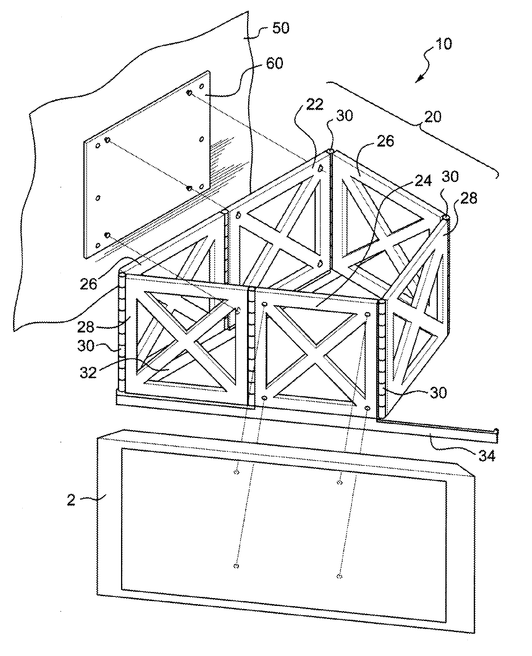
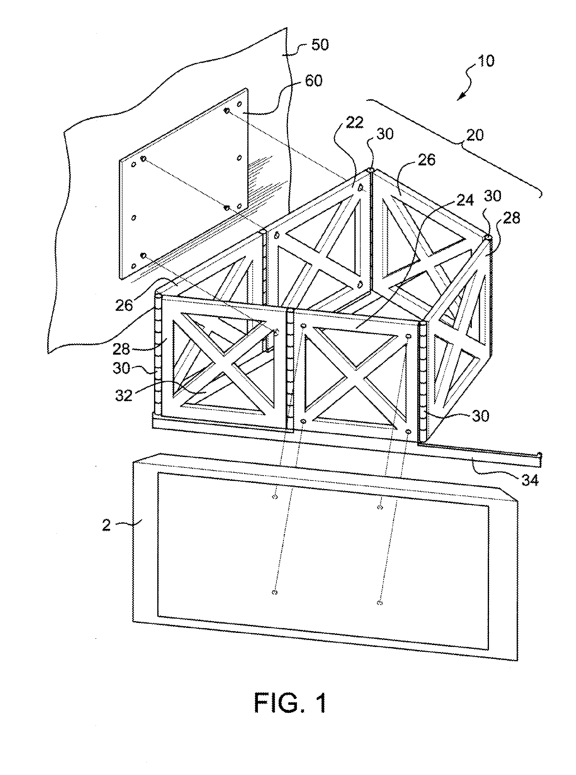
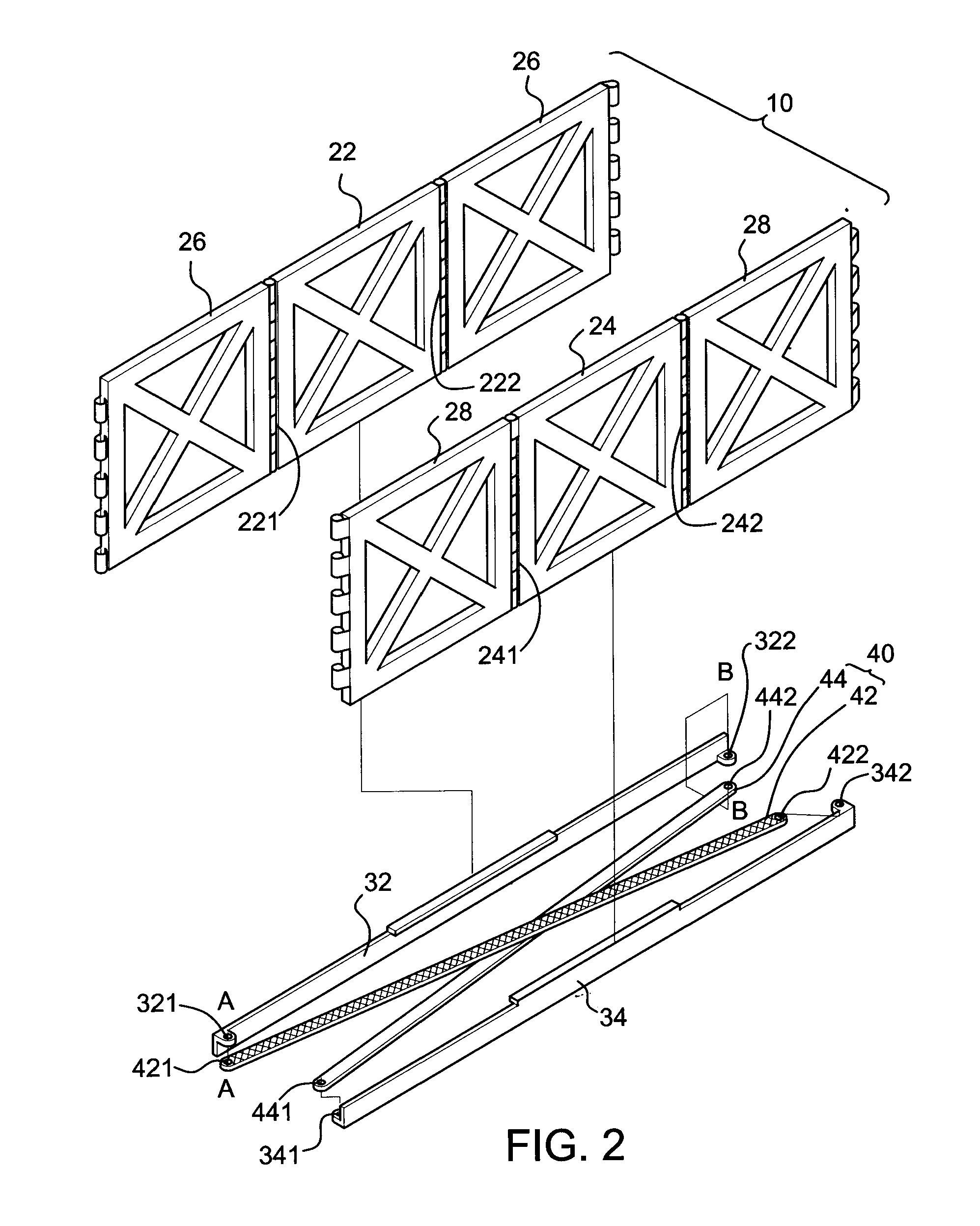
[0027]FIG. 1 shows a first embodiment of the flat panel display mounting device 10 and FIG. 2 shows an exploded view thereof. The device 10 comprises a support mechanism 20, which further comprises a base support panel member 22, a display support panel member 24, and two pairs of rotatable support panel members 26 and 28. The base support panel member 22 is fixed to a support surface or on a wall 50 via a mounting plate 60 by means of, for example, screws. The display support panel member 24 is adapted to support a flat panel display 2. The display support panel member 24 is pivotally connected to the base support panel member 22 via the two pairs of rotatable support panel members 26 and 28 by means of, for example, hinges 30. Specifically, the two pairs of rotatable support panel members 26 and 28 are configured in the following manner: one of the two pairs of the rotatable support panel members 26 and 28 is pivotally connected to the left edge 221 of the base support panel membe...


PUM


Abstract

A flat panel display mounting device for securing a flat panel display, such as an LCD or plasma television, to a support surface, such as a wall, is disclosed. The flat panel display mounting device comprises a plurality of members in the form of support panels pivotally connected together and a rotation control mechanism connected thereto so that the flat panel display mounted on the device can be rotated to a desired angle and the center of gravity of the flat panel display during rotation can be maintained as close to the support surface as possible, so as not to generate additional burden to the flat panel display mounting device.

Description

CROSS-REFERENCE TO RELATED APPLICATIONS[0001]This application claims priority to, and is a Divisional of, U.S. application Ser. No. 11 / 852,536, filed on Sep. 10, 2007, now pending, which is hereby incorporated by reference in its entirety.[0002]Although incorporated by reference in its entirety, no arguments or disclaimers made in the parent application apply to this divisional application. Any disclaimer that may have occurred during the prosecution of the above-referenced application(s) is hereby expressly rescinded. Consequently, the Patent Office is asked to review the new set of claims in view of all of the prior art of record and any search that the Office deems appropriate.FIELD OF THE INVENTION[0003]The present invention relates to a flat panel display mounting device, and more particularly to such a device having planar structure for adjusting the viewing angle of the flat panel display mounted thereon without translational movement.BACKGROUND OF THE INVENTION[0004]Flat pan...

Claims


Application Information

Patent Timeline
Patent Type & Authority Applications(United States)
IPC IPC(8): A47F5/08
CPCF16M11/045F16M13/02F16M11/08F16M11/048Y10S248/917Y10S248/919
Inventor WU, MIN-CHUANYU, HUNG-HSIN
Owner LEW ANDREW H
Learn More