AI technical title is built by PatSnap AI team. It summarizes the technical point description of the patent document.
a micro-wire and wire technology, applied in the field of transparent conductors, can solve the problems of limited current-carrying capacity of such electrodes, limited power supply to pixel elements, and limited substrate materials, so as to improve conductivity and performan
Active Publication Date: 2015-02-03
EASTMAN KODAK CO
View PDF15 Cites 2 Cited by
Summary
Abstract
Description
Claims
Application Information
AI Technical Summary
This helps you quickly interpret patents by identifying the three key elements:
Problems solved by technology
Method used
Benefits of technology
Benefits of technology
[0022]The present invention provides improved conductivity and performance for transparent micro-wire electrodes in electronic devices and mutually capacitive touch screens without deleteriously affecting the transparency or function of the apparatus.
Problems solved by technology
However, the current-carrying capacity of such electrodes is limited, thereby limiting the amount of power that can be supplied to the pixel elements.
Moreover, the substrate materials are limited by the deposition process (e.g. sputtering).
Thicker layers of metal oxides or metals increase conductivity but reduce the transparency of the electrodes.
However, such wires are not transparent and thus the number and size of the wires limits the substrate transparency as the overall conductivity of the wires increases.
Transparent conductive metal oxides are well known in the display and touch screen industry and have a number of disadvantages, including inadequate transparency and conductivity, high manufacturing costs due to vacuum processes and a tendency to crack under mechanical or environmental stress.
Further, the high demand for indium has significantly increased the price of this raw material.
Method used
Image
Click on the blue label to locate the original text in one second.
Reading with bidirectional positioning of images and text.
Examples
Embodiment Construction
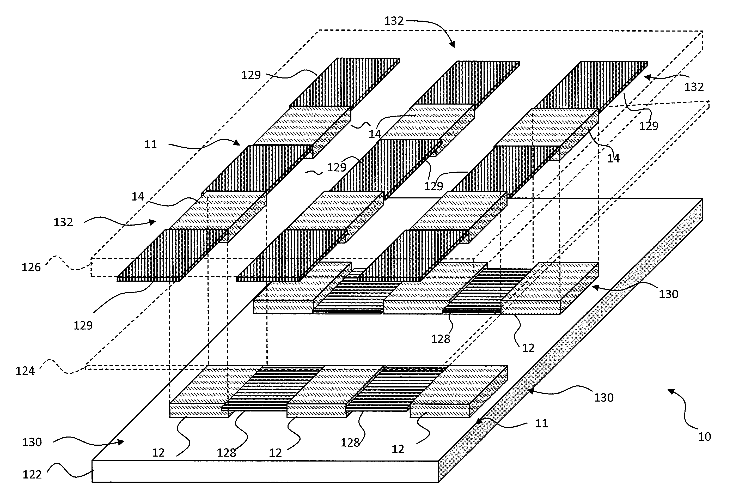
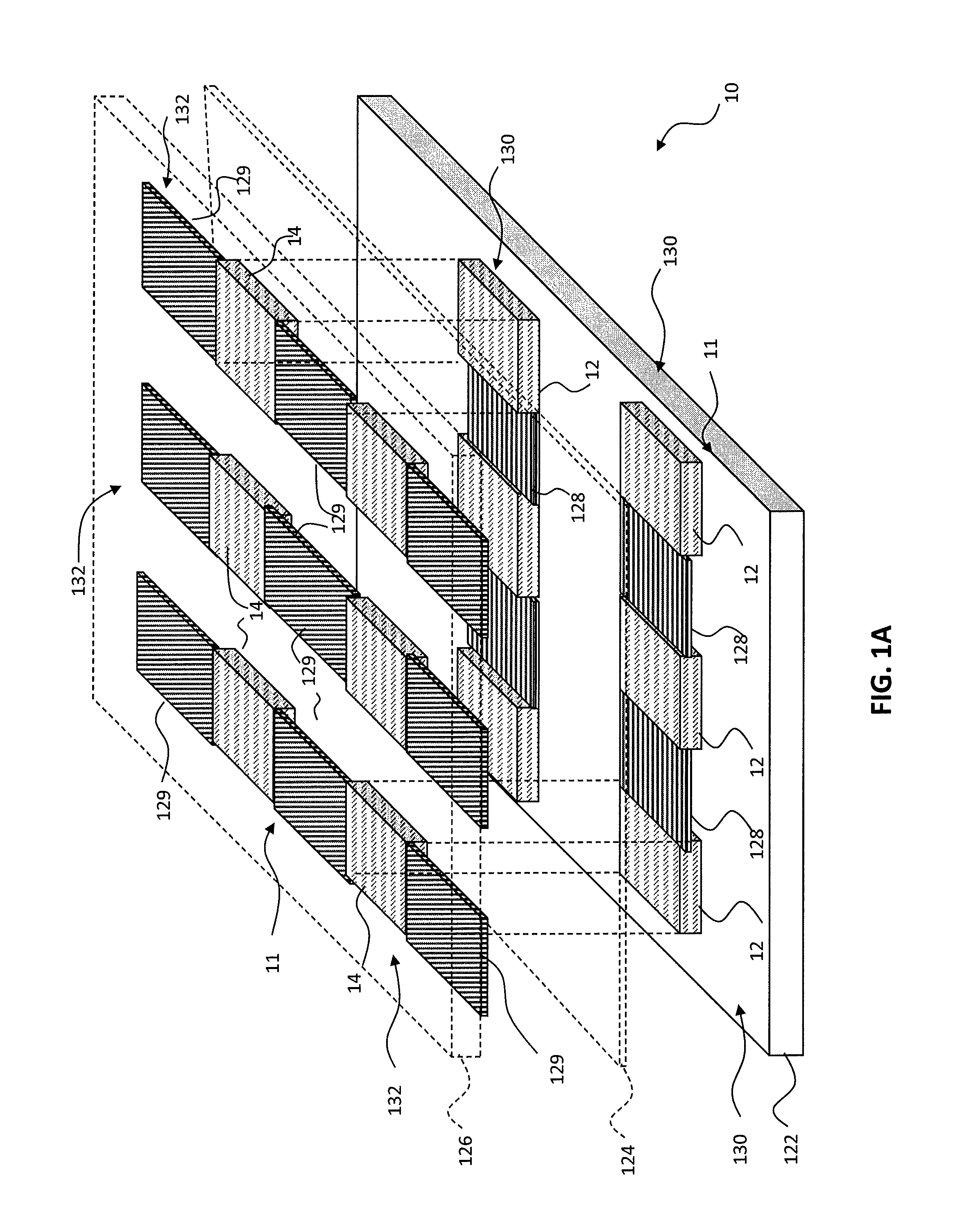
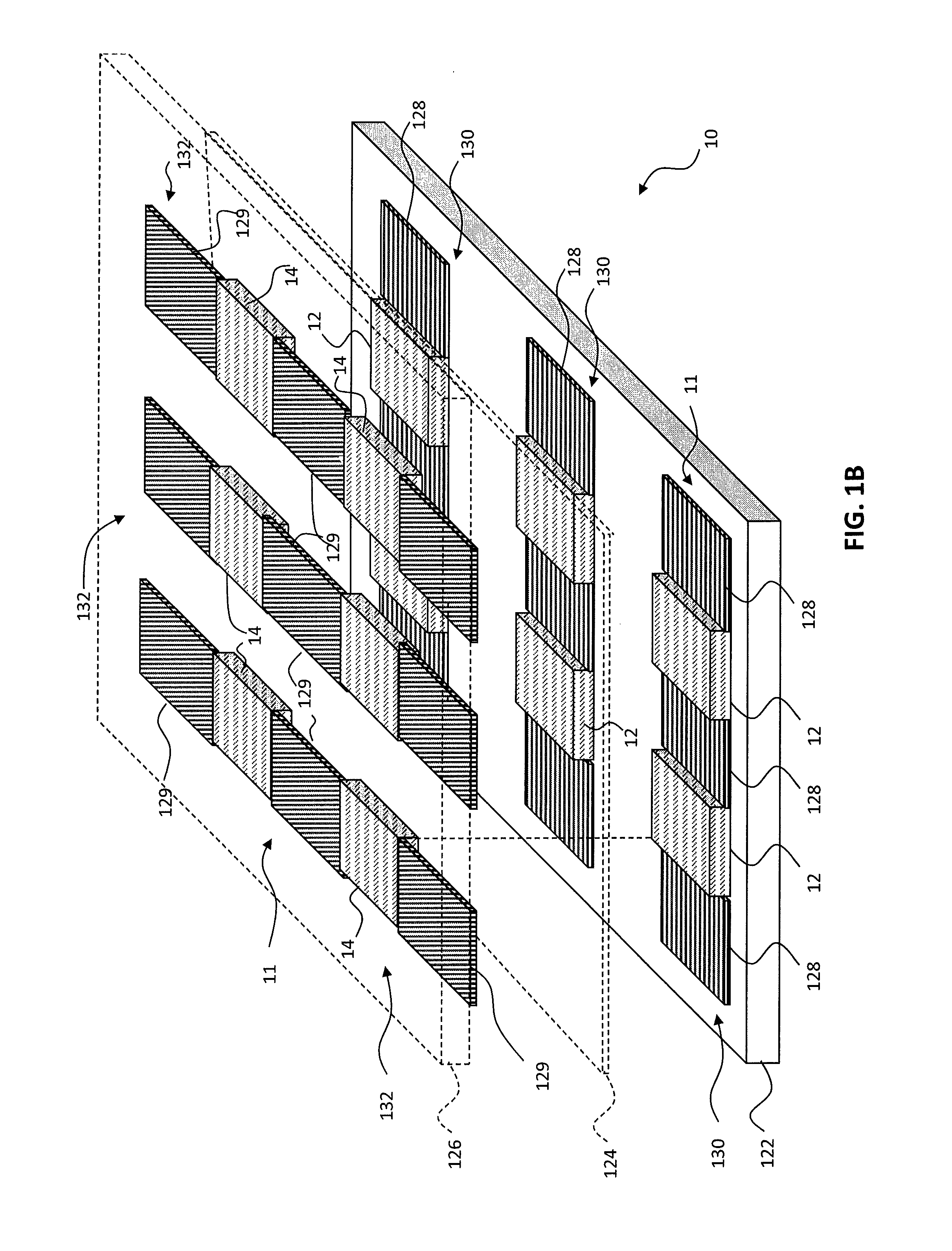
[0045]Referring to FIGS. 1A and 1B, according to an embodiment of the present invention, a touch-responsive capacitive apparatus 10 includes a first transparent substrate 122. A plurality of first pad areas 128 and first interstitial areas 12 are formed in a first micro-wire layer and a plurality of second pad areas 129 and second interstitial areas 14 are formed in a second micro-wire layer. Pairs of first and second pad areas 128, 129 define corresponding touch-responsive capacitors. The first or second micro-wire layers are supported by the first transparent substrate 122. Thus, the first or second pad areas 128, 129 and first or second interstitial areas 12, 14 can be formed upon one or the other sides of the first transparent substrate 122 or on layers located upon, over, under, or adjacent to one or the other sides of the first transparent substrate 122. As illustrated in the example of FIGS. 1A and 1B, the first pad areas 128 and first interstitial areas 12 are formed over th...
PUM
Property
Measurement
Unit
transparent
aaaaa
aaaaa
transparency
aaaaa
aaaaa
transparent
aaaaa
aaaaa
Abstract
A method of making a transparent touch-responsive capacitor apparatus includes providing a transparent conductor precursor structure including a transparent substrate, a first precursor material layer formed over the transparent substrate and a second precursor material layer formed on the first precursor material layer; forming a electrically connected first micro-wires in the first and second precursor material layers; forming electrically connected second micro-wires in a precursor material layer electrically connected to the first micro-wires; and wherein the height of at least a portion of the first micro-wires is greater than the height of at least a portion of the second micro-wires, and wherein the total area occupied by the first micro-wires is less than 15% of the first transparent conductor area and the total area occupied by the second micro-wires is less than 15% of the second transparent conductor area.
Description
CROSS REFERENCE TO RELATED APPLICATIONS[0001]Reference is made to commonly-assigned, co-pending U.S. patent application Ser. No. 13 / 406,658 filed Feb. 28, 2012, entitled “TRANSPARENT TOUCH-RESPONSIVE CAPACITOR WITH VARIABLE-HEIGHT MICRO-WIRES” by Ronald S. Cok; U.S. patent application Ser. No. 13 / 406,827 filed Feb. 28, 2012, filed concurrently herewith, entitled “PATTERN-WISE DEFINING MICRO-WIRES WITH DIFFERENT HEIGHTS”, by Ronald S. Cok; U.S. patent application Ser. No. 13 / 406,845 filed Feb. 28, 2012, entitled “ELECTRONIC DEVICE HAVING METALLIC MICRO-WIRES”, by Ronald S. Cok, et al.; U.S. patent application Ser. No. 13 / 406,867 filed Feb. 28, 2012, filed concurrently herewith, entitled “TOUCH SCREEN WITH DUMMY MICRO-WIRES”, by Ronald S. Cok, et al., and U.S. patent application Ser. No. 13 / 406,649 filed Feb. 28, 2012, entitled “TRANSPARENT TOUCH-RESPONSIVE CAPACITOR WITH VARIABLE-PATTERN MICRO-WIRES”, by Ronald S. Cok, the disclosures of which are incorporated herein.FIELD OF THE INV...
Claims
Application Information
Patent Timeline
Application Date:The date an application was filed.
Publication Date:The date a patent or application was officially published.
First Publication Date:The earliest publication date of a patent with the same application number.
Issue Date:Publication date of the patent grant document.
PCT Entry Date:The Entry date of PCT National Phase.
Estimated Expiry Date:The statutory expiry date of a patent right according to the Patent Law, and it is the longest term of protection that the patent right can achieve without the termination of the patent right due to other reasons(Term extension factor has been taken into account ).
Invalid Date:Actual expiry date is based on effective date or publication date of legal transaction data of invalid patent.

