Supercharge Your Innovation With Domain-Expert AI Agents!

Method of making a transparent conductor structure

a conductor and transparent technology, applied in capacitor manufacturing, variable capacitors, instruments, etc., can solve the problems of limited current-carrying capacity of such electrodes, limited power supply to pixel elements, and limited substrate materials, so as to improve conductivity and performance

Active Publication Date: 2014-09-02
EASTMAN KODAK CO
View PDF25 Cites 5 Cited by
  • Summary
  • Abstract
  • Description
  • Claims
  • Application Information

AI Technical Summary

Benefits of technology

The present invention improves the conductivity and performance of transparent micro-wire electrodes used in electronic devices and mutually capacitive touch screens without affecting their transparency or function.

Problems solved by technology

However, the current-carrying capacity of such electrodes is limited, thereby limiting the amount of power that can be supplied to the pixel elements.
Moreover, the substrate materials are limited by the deposition process (e.g. sputtering).
Thicker layers of metal oxides or metals increase conductivity but reduce the transparency of the electrodes.
However, such wires are not transparent and thus the number and size of the wires limits the substrate transparency as the overall conductivity of the wires increases.
Transparent conductive metal oxides are well known in the display and touch screen industry and have a number of disadvantages, including inadequate transparency and conductivity, high manufacturing costs due to vacuum processes and a tendency to crack under mechanical or environmental stress.
Further, the high demand for indium has significantly increased the price of this raw material.

Method used


Image

  • Method of making a transparent conductor structure
  • Method of making a transparent conductor structure
  • Method of making a transparent conductor structure

Examples


Embodiment Construction

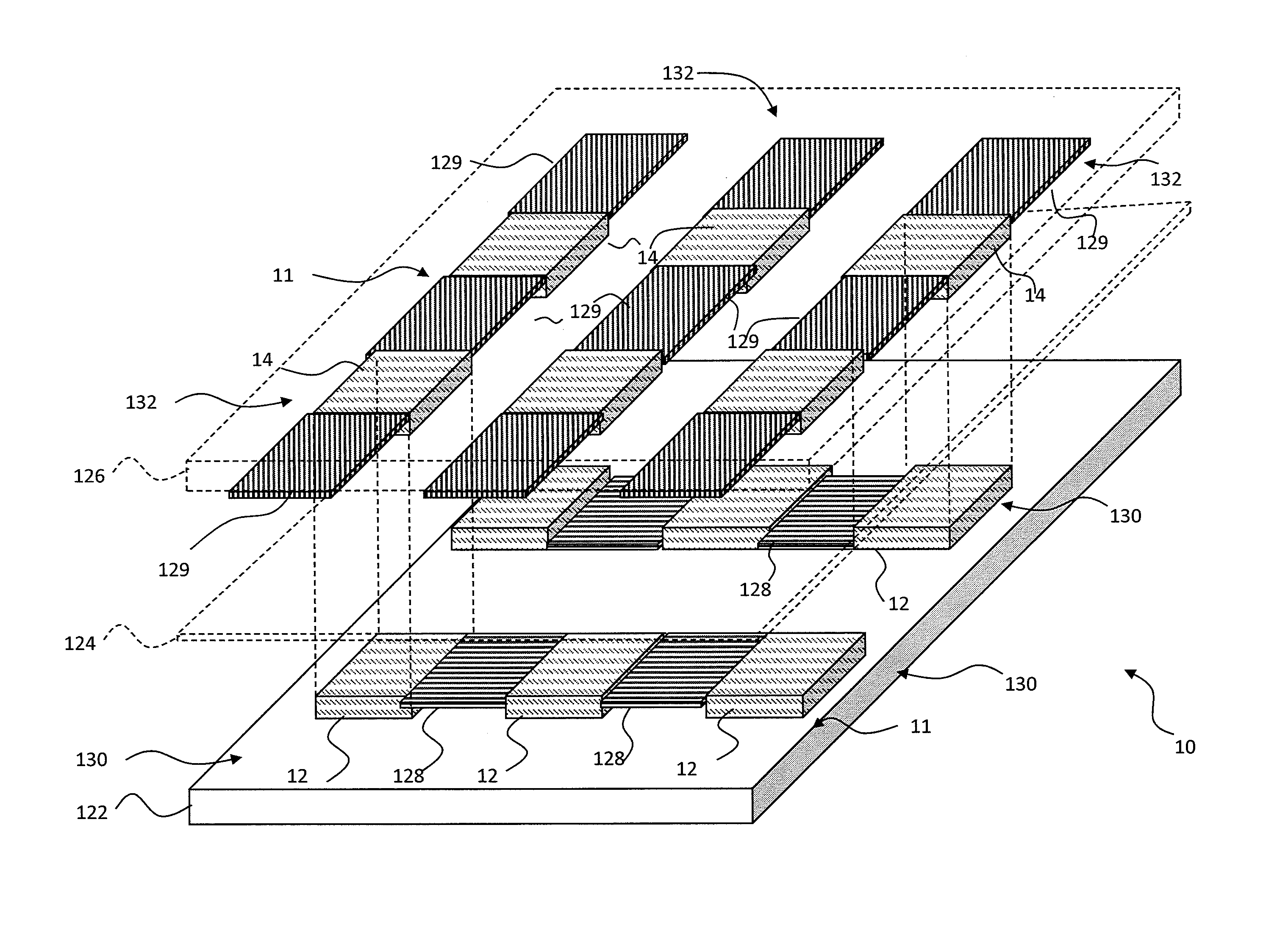
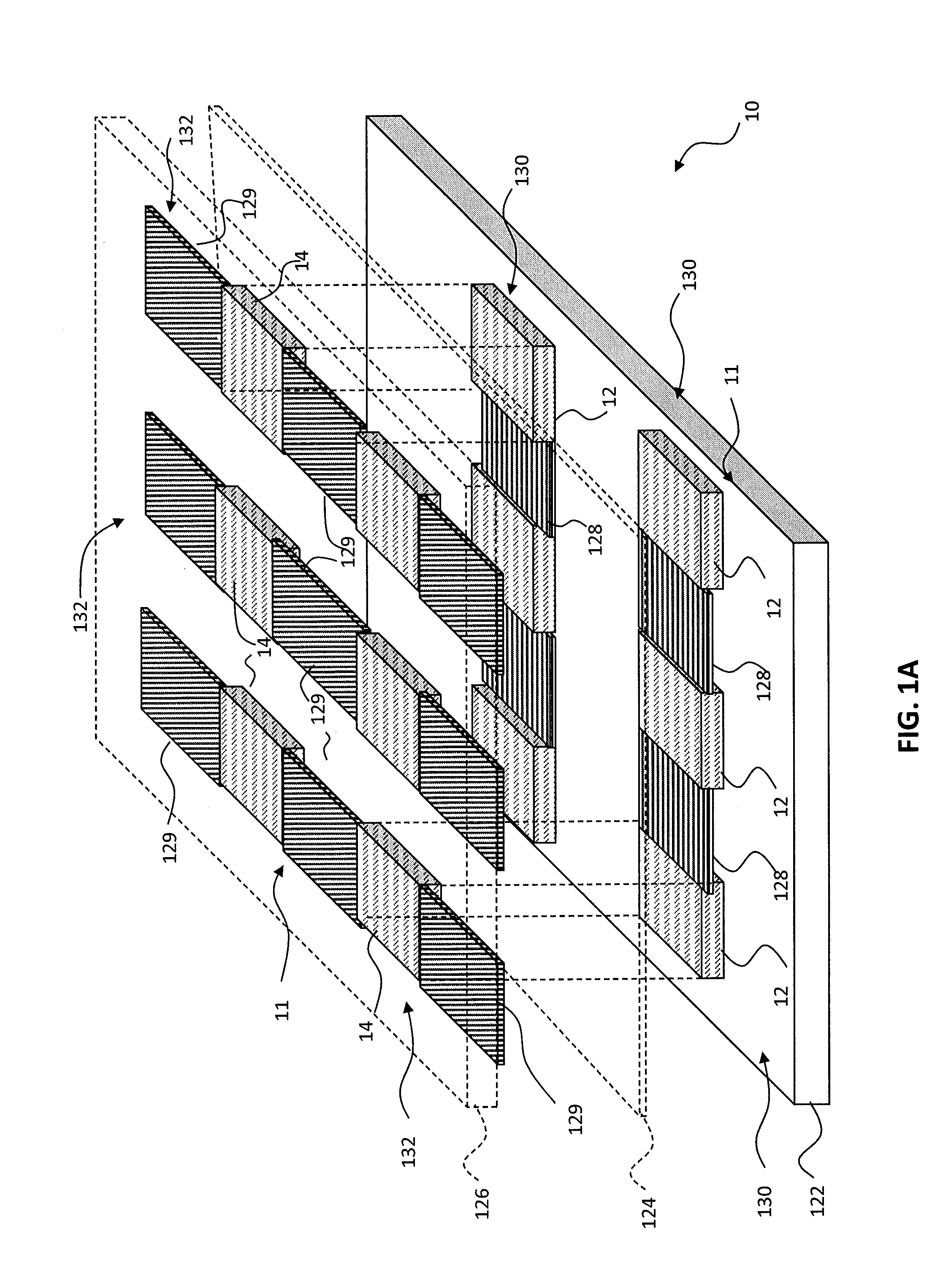
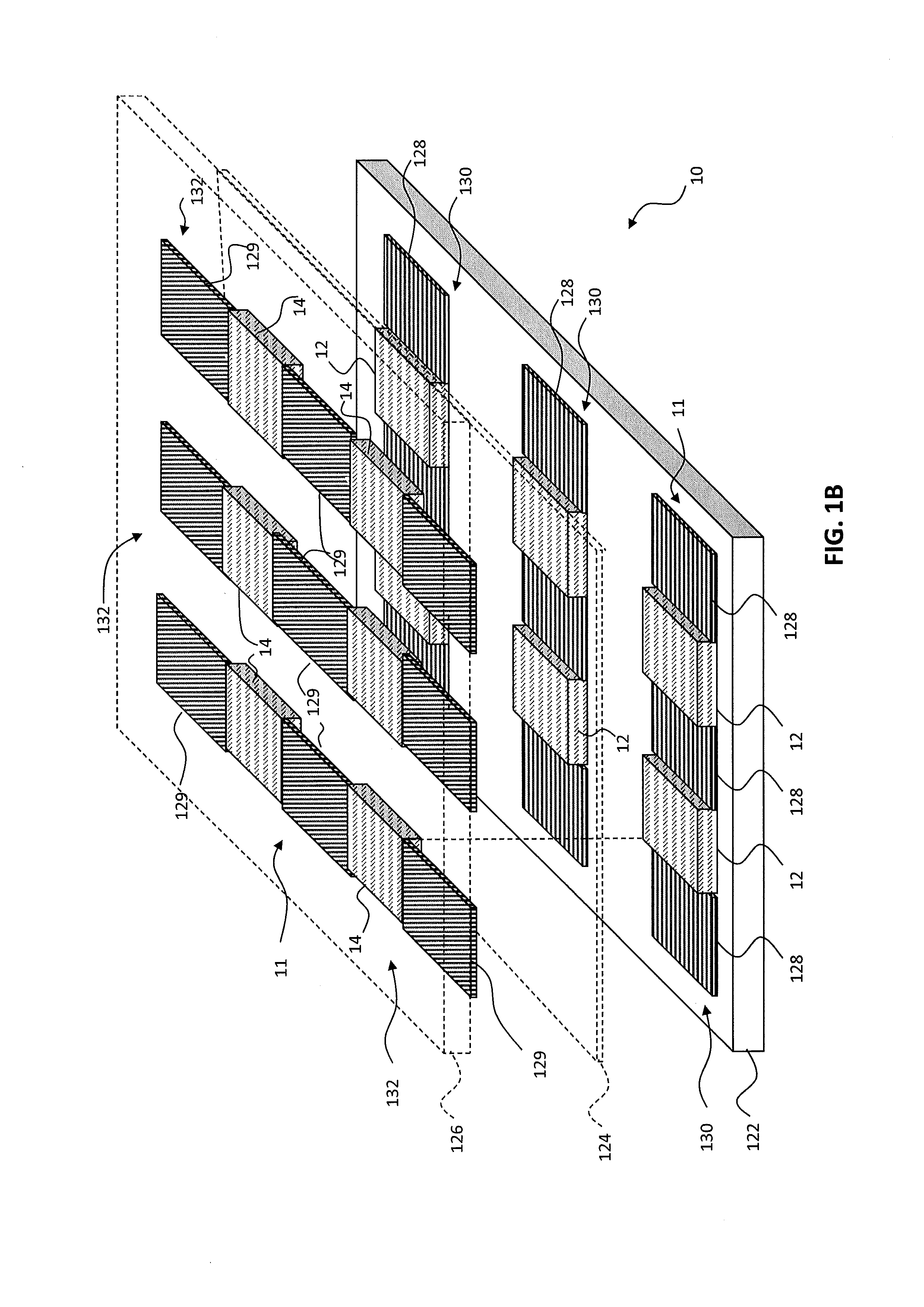
[0045]Referring to FIGS. 1A and 1B, according to an embodiment of the present invention, a touch-responsive capacitive apparatus 10 includes a first transparent substrate 122. A plurality of first pad areas 128 and first interstitial areas 12 are formed in a first micro-wire layer and a plurality of second pad areas 129 and second interstitial areas 14 are formed in a second micro-wire layer. Pairs of first and second pad areas 128, 129 define corresponding touch-responsive capacitors. The first or second micro-wire layers are supported by the first transparent substrate 122. Thus, the first or second pad areas 128, 129 and first or second interstitial areas 12, 14 can be formed upon one or the other sides of the first transparent substrate 122 or on layers located upon, over, under, or adjacent to one or the other sides of the first transparent substrate 122. As illustrated in the example of FIGS. 1A and 1B, the first pad areas 128 and first interstitial areas 12 are formed over th...


PUM

PropertyMeasurementUnit
transparencyaaaaaaaaaa
transparentaaaaaaaaaa
distanceaaaaaaaaaa

Abstract

A method of making a transparent touch-responsive capacitor apparatus includes providing a transparent substrate having a material layer formed over the transparent substrate; pattern-wise defining electrically connected first micro-wires over the transparent substrate in a plurality of first transparent conductor areas in the materials layer; pattern-wise defining electrically connected second micro-wires over the transparent substrate in a plurality of second transparent conductor areas spaced apart from the first transparent conductor areas in the material layer, the first micro-wires electrically connected to the second micro-wires; and wherein the height of at least a portion of the first micro-wires is greater than the height of at least a portion of the second micro-wires and the total area occupied by the first micro-wires is less than 15% of the first transparent conductor area and the total area occupied by the second micro-wires is less than 15% of the second transparent conductor area.

Description

CROSS REFERENCE TO RELATED APPLICATIONS[0001]Reference is made to commonly-assigned, co-pending U.S. patent application Ser. No. 13 / 406,658 filed Feb. 28, 2012, entitled “TRANSPARENT TOUCH-RESPONSIVE CAPACITOR WITH VARIABLE-HEIGHT MICRO-WIRES” by Ronald S. Cok; U.S. patent application Ser. No. 13 / 406,665 filed Feb. 28, 2012, entitled “MAKING MICRO-WIRES WITH DIFFERENT HEIGHTS” by Ronald S. Cok, et al.; U.S. patent application Ser. No. 13 / 406,845 filed Feb. 28, 2012, entitled “ELECTRONIC DEVICE HAVING METALLIC MICRO-WIRES”, by Ronald S. Cok, et al.; U.S. patent application Ser. No. 13 / 406,867 filed Feb. 28, 2012, entitled “TOUCH SCREEN WITH DUMMY MICRO-WIRES”, by Ronald S. Cok, et al., and U.S. patent application Ser. No. 13 / 406,649 filed Feb. 28, 2012, entitled “TRANSPARENT TOUCH-RESPONSIVE CAPACITOR WITH VARIABLE-PATTERN MICRO-WIRES”, by Ronald S. Cok, the disclosures of which are incorporated herein.FIELD OF THE INVENTION[0002]The present invention relates to transparent conductor...

Claims


Application Information

Patent Timeline
Patent Type & Authority Patents(United States)
IPC IPC(8): H01R43/00
CPCH01G13/00H01G4/38G06F3/0445G06F3/0446G06F2203/04103G06F2203/04112Y10T29/43Y10T29/49002Y10T29/49117Y10T29/49156Y10T29/49162G06F3/0443
Inventor COK, RONALD, STEVEN
Owner EASTMAN KODAK CO
Features
  • R&D
  • Intellectual Property
  • Life Sciences
  • Materials
  • Tech Scout
  • Unparalleled Data Quality
  • Higher Quality Content
  • 60% Fewer Hallucinations
Learn More