Electrical connector having shielded differential pairs

a technology of electric connectors and differential pairs, applied in the direction of coupling device connections, coupling protective earth/shielding arrangements, two-part coupling devices, etc., can solve the problems of insufficient electrical connectors, signal loss and/or signal degradation in known electrical systems, and further strain on performan

Inactive Publication Date: 2015-02-24
TYCO ELECTRONICS LOGISTICS AG (CH)
View PDF11 Cites 6 Cited by
  • Summary
  • Abstract
  • Description
  • Claims
  • Application Information

AI Technical Summary

Problems solved by technology

However, as speed and performance demands increase, known electrical connectors are proving to be insufficient.
For example, signal loss and / or signal degradation is a problem in known electrical systems.
However, increasing the density of signal conductors and / or reducing the size of the electrical connectors can cause further strains on performance.
In addition to the above challenges, certain types of connector configurations, such as right-angle configurations, may also cause problems with the performance and implementation of electrical connectors.
However, metalized housings can be costly to manufacture.

Method used


Image

  • Electrical connector having shielded differential pairs
  • Electrical connector having shielded differential pairs
  • Electrical connector having shielded differential pairs

Examples


Embodiment Construction

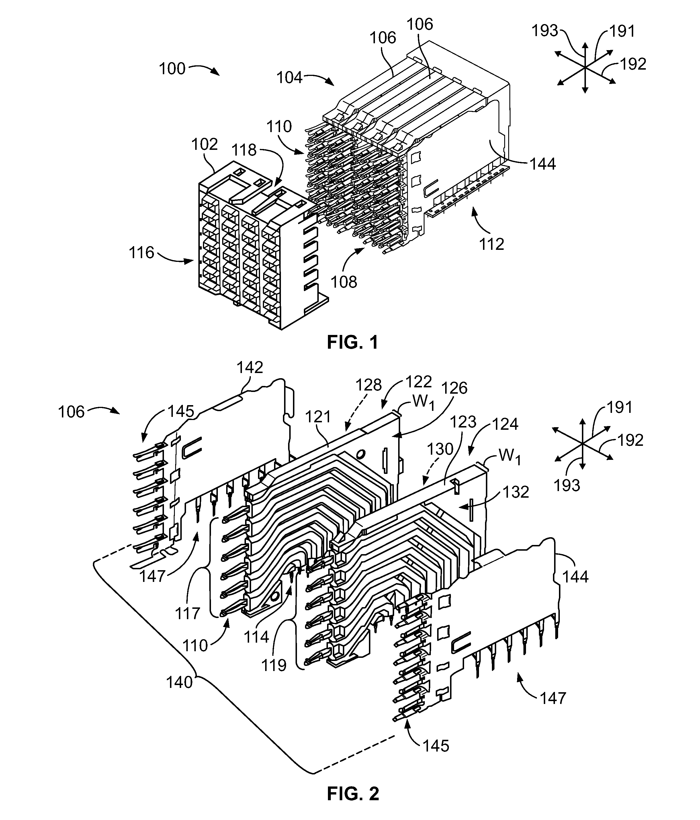
[0016]FIG. 1 is a partially exploded view of an electrical connector 100 formed in accordance with one embodiment. The electrical connector is oriented with respect to mutually perpendicular axes 191-193, including a mating axis 191, a lateral axis 192, and an orientation axis 193. In the illustrated embodiment, the electrical connector 100 includes a connector housing 102 and a module assembly 104 that is configured to be coupled to and held by the connector housing 102. The module assembly 104 may include one or more contact modules 106. For example, a plurality of the contact modules 106 may be stacked side-by-side and held by the connector housing 102. Each of the contact modules 106 includes a terminal end or side 108 where a plurality of exposed conductor beams 110 are located, and a mounting end or side 112 where a plurality of exposed conductor tails 114 (shown in FIG. 2) are located.

[0017]In the illustrated embodiment, the terminal end 108 and the mounting end 112 are orien...


PUM


Abstract

An electrical connector including a connector housing having a mating face that is configured to engage a mating connector. The electrical connector also includes a contact module that is held by the connector housing and that includes differential pairs of signal conductors. The contact module also includes dielectric ribs that encase corresponding signal conductors. The dielectric ribs are spaced apart from one another. The contact module also includes guard conductors that extend between and couple to adjacent dielectric ribs. The contact module also includes a conductive layer that is disposed on the dielectric ribs and the guard conductors. The conductive layer is electrically coupled to the guard conductors.

Description

BACKGROUND OF THE INVENTION[0001]The subject matter herein relates generally to an electrical connector having a plurality of differential pairs of signal conductors for transmitting data signals.[0002]Electrical connector systems, such as those used in networking and telecommunication systems, utilize receptacle and header connectors to interconnect components of the system, such as a motherboard and daughtercard. However, as speed and performance demands increase, known electrical connectors are proving to be insufficient. For example, signal loss and / or signal degradation is a problem in known electrical systems. There is also a desire to increase the density of signal conductors to increase throughput of the electrical system, without an appreciable increase in size of the electrical connectors. In fact, a decrease in the sizes of the electrical connectors is desired. However, increasing the density of signal conductors and / or reducing the size of the electrical connectors can c...

Claims


Application Information

Patent Timeline
Patent Type & Authority Patents(United States)
IPC IPC(8): H01R13/648H01R12/50H01R13/6599
CPCH01R13/6599H01R23/7073H01R13/6463H01R13/6477H01R13/6587H01R12/00
Inventor JEON, MYOUNGSOO
Owner TYCO ELECTRONICS LOGISTICS AG (CH)
Why Eureka
Try Eureka