Module used for stacking thin plate panels

a technology of modules and thin plates, applied in the direction of machine supports, transportation and packaging, packaging goods types, etc., can solve the problems of difficult to stably stack a difficult to ensure the load transmitting area on the upper portion, and difficult to stably stack the plurality of thin panels in the vertical direction. stably stored or conveyed efficient and stably stacked

Inactive Publication Date: 2015-03-31
HITACHI TRANSPORT SYST LTD +1
View PDF13 Cites 4 Cited by
  • Summary
  • Abstract
  • Description
  • Claims
  • Application Information

AI Technical Summary

Benefits of technology

[0009]In view of the technical problems described above, it is an object of the present invention to provide a module used for stacking thin panels, which allows a plurality of thin panels to be efficiently and stably stacked in the vertical direction. In view of the technical problems described above, it is an object of the present invention to provide a module used for stacking thin panels that allows thin panels, which are stacked in the vertical direction in a non-contact manner, to be stably stored or conveyed. In view of the technical problems described above, it is an object of the present invention to provide a module used for stacking thin panels that allows a plurality of thin panels, which are stacked in the vertical direction in a non-contact manner via a frame body placed on a peripheral edge portion of each panel, to be efficiently and stably stacked in the vertical direction. In view of the technical problems described above, it is an object of the present invention to provide a module used for stacking thin panels that does not lead to increase in forming cost and is useful for conveying the thin panels attached to the frame bodies to and from a place for stacking the thin panels, and prevents the frame body from being removed from the module, in the case where the plurality of thin panels are stacked via a frame body placed on a peripheral edge portion of each panel, in the vertical direction.Solutions to the Problems

Problems solved by technology

However, the following technical problems arise in this module.
Firstly, it is difficult to stack a plurality of the thin panels in the vertical direction stably because a positioning portion for the thin panel and a load transmitting portion for the thin panel are not separated with each other.
Accordingly, it is difficult to sufficiently ensure load transmitting areas on the upper portion and the lower portion of the molded member because the protrusion and the recess exist.
This makes it difficult to stably stack the plurality of the thin panels in the vertical direction.
Secondly, the module requires a considerable amount of material, and this leads to increase in cost because a support portion for the thin panel and the positioning portion for the thin panel are separated with each other.
Thirdly, it is difficult to efficiently stack the plurality of thin panels in the vertical direction.
In this respect, it is difficult to place the module at each of the four corners of the plurality of thin panels in advance and then stack the thin panels, which has the modules at the four corners, on the top surface of the pallet.
This might cause collapse of the modules in a columnar shape depending on the circumstance.
Fourthly, the protection for the thin panels is not sufficient especially when the thin panels with frames are stacked in the vertical direction.
This may cause damage of the thin panel, and may cause breakage of the thin panel depending on the circumstance.
However, this additionally requires the border section 5 and leads to increase in cost for forming the module.

Method used


Image

  • Module used for stacking thin plate panels
  • Module used for stacking thin plate panels
  • Module used for stacking thin plate panels

Examples


fourth embodiment

[0066]A fourth embodiment of the present invention will be described in detail below. In the following description, like reference numerals designate elements corresponding or identical to those in the first embodiment, and such elements will not be further elaborated here. A description will be given on features of this embodiment in detail.

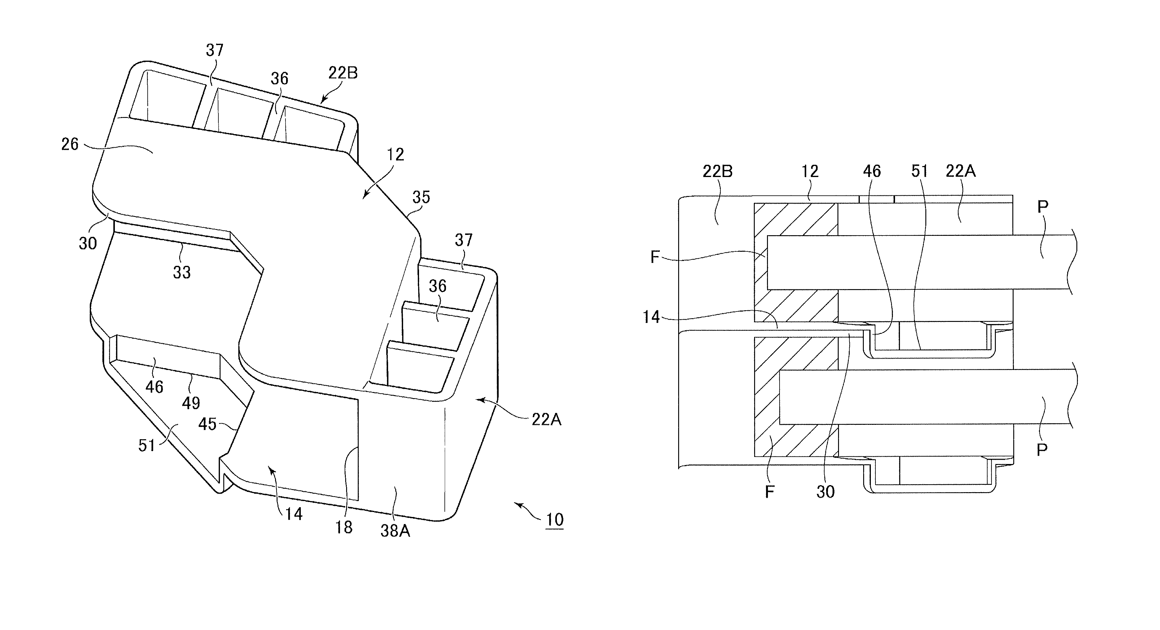
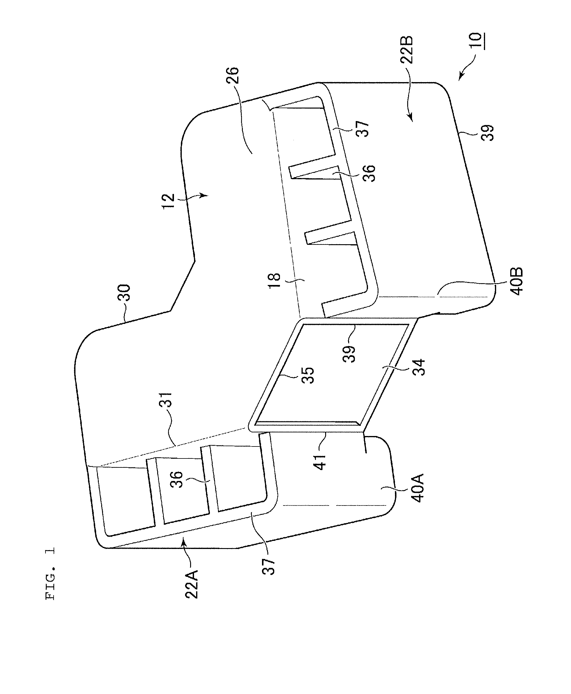
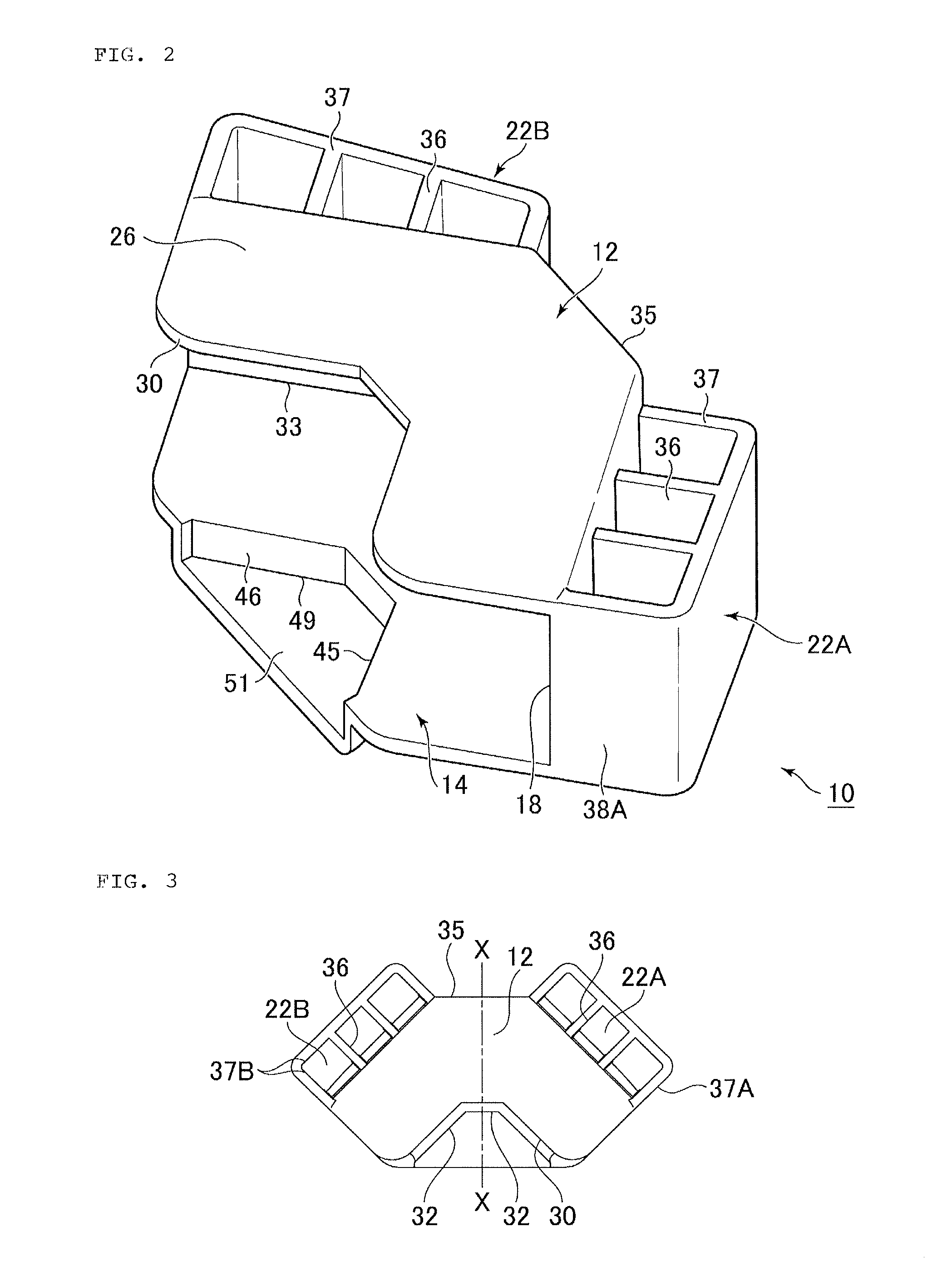
[0067]A module 10 according to this embodiment has following features. A thin panel P without a frame body is a target of this embodiment. The module 10 according to this embodiment is a modification of the module according to the first embodiment. Specifically, a middle plate-shaped body 202 is disposed between the upper plate-shaped body 12 and the lower plate-shaped body 14, and longitudinal ribs 204 are disposed to extend between the upper plate-shaped body 12 and the middle plate-shaped body 202. As illustrated in FIG. 12 and FIG. 13, the middle plate-shaped body 202 cooperates with the lower plate-shaped body 14 to sandwich the thin panel ...


PUM


Abstract

The present invention provides a module used for stacking thin panels that allows for stacking of a plurality of thin panels in the vertical direction efficiently and stably. The module includes a sandwiching support portion, a load transmitting portion, and a positioning portion. The sandwiching support portion sandwiches and supports the thin panel. The load transmitting portion is coupled with the sandwiching support portion, and transmits the weight of the thin panel in the vertical direction. The positioning portion relatively positions thin panels, which are stacked in the vertical direction, in the horizontal direction. The sandwiching support portion includes a lower plate-shaped body and a vertical wall. The lower plate-shaped body is disposed on a lower portion of the module. The vertical wall extends upward from an outer edge of the lower plate-shaped body to form an approximately C-shaped cross-sectional surface in conjunction with the lower plate-shaped body. The load transmitting portion includes a load transmitting surface, which is formed outward from an outer surface of the vertical wall. The positioning portion includes an inner lock portion on an inner edge of the lower plate-shaped body and an outer lock portion on the outer edge of the lower plate-shaped body. The inner lock portion is contactable with an inner edge of an upper portion of the module. The outer lock portion is contactable with an outer edge of the upper portion of the module.

Description

CROSS-REFERENCE TO RELATED APPLICATIONS[0001]The present patent application is a nationalization of International application No. PCT / JP2011 / 007050, filed Dec. 16, 2011 which is based on, and claims priority from, Japanese Application No. 2010-281077, filed Dec. 16, 2010 and Japanese Application No. 2010-281078, filed Dec. 16, 2010, all of which are incorporated herein by reference in their entireties.TECHNICAL FIELD[0002]The present invention relates to a module used for stacking thin panels and a method of stacking the thin panels. More specifically, the present invention relates to a module used for stacking thin panels, which allows for stacking of a plurality of thin panels in the vertical direction efficiently and stably, a method of stacking the thin panels with the module, and a module used for stacking thin panels, which allows for stable storage or conveyance of thin panels stacked in the vertical direction in a non-contact manner.BACKGROUND ART[0003]Conventionally, a modu...

Claims


Application Information

Patent Timeline
Patent Type & Authority Patents(United States)
IPC IPC(8): B65D85/48B65D57/00B65D81/05B65D85/30F16M13/00H01L21/673H01L31/02
CPCF16M13/00B65D57/00H01L21/6734B65D81/057B65D85/30H01L31/02B65D2585/86B65D57/004
Inventor KASHIMA, NOBUYUKIKOBAYASHI, HIROSHIMATSUE, TAKESHIHASHIMOTO, HIROYUKIYOSHIDA, KOICHIRO
Owner HITACHI TRANSPORT SYST LTD
Why Eureka
Try Eureka