Module for stacking thin panels and method of stacking thin panels

a technology of modules and thin panels, applied in the direction of stacking articles, packaging goods types, transportation and packaging, etc., can solve the problems of damage to the stacked thin panels, the difficulty of stacked thin panels, and the difficulty of related art modules in efficiently and stably stacking a plurality of thin panels in a vertical direction,

Inactive Publication Date: 2014-09-30
KYORAKU CO LTD
View PDF17 Cites 15 Cited by
  • Summary
  • Abstract
  • Description
  • Claims
  • Application Information

AI Technical Summary

Benefits of technology

[0014]Moreover, another object of the present invention in light of the above technical problems is to provide a module for stacking a plurality of thin panels and a method of stacking thin panels, the module and the method allowing the plural thin panels to be efficiently and stably stacked in a vertical direction.
[0016]According to such a configuration of the module for stacking the thin panels, when the plural thin panels are stacked, the load receiving surface in an upper portion of the module that is used for supporting the thin panel from below is arranged on an outer side of the thin panel. On this load receiving surface, the load releasing surface in a lower portion of a next module is placed. The next module supports the thin plate from below, in such a manner that a load of the thin panel is transferred between the upper and lower modules. Moreover, an outer surface of the protrusion portion protruding downward from a lower portion of the upper module abuts on an upper inner surface of the lower module from an inner side thereof, thereby regulating relative movement of the upper module to an outer side of the lower module. Also, since the thin panel is provided between the modules, relative movement of the upper module to an inner side of the lower module is regulated. That is, the module is prevented from being dropped off caused by shift in a horizontal direction. Accordingly, unlike the known manner, the load receiving surface and the load releasing surface forming the load transfer surface do not have recessed-raised shaped positioning portions. Consequently, a size of a load transfer area does not have to be reduced to regulate relative movement of the upper module to an outer side and an inner side of the lower module. Therefore, an adequate area for load transfer of the thin panel can be secured.
[0018]According to such a configuration of the module for stacking the thin panels, a thin panel is insertable between the lower plate-shaped body and the upper plate-shaped body from the opening portion of the pocket having the generally U-shaped cross-section of the sandwich-and-support portion, such that the module sandwiches and supports the thin panel. The load releasing surface of the upper module is to be placed on the load receiving surface of the lower module. Such placement allows the load transfer between the module sandwiching and supporting the lower thin panel and the module sandwiching and supporting the upper thin panel. Further, an outer surface of the protrusion portion protruding downward from a lower portion of the upper module is to abut on an upper inner surface of the lower module from an inner side thereof, thereby determining a horizontal position of the upper module by the lower module. Therefore, the thin panels are capable of being efficiently and stably stacked in a vertical direction.
[0026]According to such a configuration of the module for stacking the thin panels, a thin panel is insertable between the lower plate-shaped body and upper plate-shaped body from the opening portion of the pocket having a generally U-shaped cross-section in the sandwich-and-support portion, such that the module sandwiches and supports the thin panel. When an upper thin panel sandwiched and supported by a module is placed on a lower thin panel sandwiched and supported by a module, a load transfer surface of the upper module is placed on a load transfer surface of the lower module, thereby transferring a load between the upper and lower modules. Further, the engagement portion provided on an inner edge of the lower plate-shaped body of the upper module is to abut on an inner edge of the upper plate-shaped body of the lower module, such that a horizontal position of the upper module is determined by the lower module. Therefore, the thin panels are capable of being stacked efficiently and stably in a vertical direction.
[0031]According to another aspect of the present invention, a method of stacking thin panel includes: preparing modules for stacking the thin panels, the modules each including a support portion for supporting a thin panel from below, a load transfer portion connected to the support portion for transferring a weight of the thin panel downward, and drop-off preventing means for regulating horizontal movement of the thin panel by using a protrusion portion protruding downward from a lower portion of the module; and stacking the thin panels in sequence by supporting corners of the plural thin panels from below by the support portions of the modules and by vertically stacking the modules in a pillar shape such that the load transfer portions transfer a weight of the thin panels downward. The stacking step includes determining a horizontal position of an upper thin panel by a lower thin panel by allowing an outer surface of the protrusion portion of an upper module to abut on an upper inner surface of a lower module from an inner side thereof at the corners of the thin panels.
[0033]According to such a method of stacking the thin panels, the modules are attached beforehand to the respective four corners of the plural thin panels to be stacked. Then, the modules attached to the four corners of the thin panels are stacked in a pillar shape. Herein, the outer surface of the protrusion portion of the upper module abuts on the upper inner surface of the lower module from the inner side thereof, thereby restricting horizontal movement of the upper module to an outer side of the lower module. Moreover, since the modules are attached to the respective four corners of the thin panels, the upper module is prevented from being slipped into an inner side of the lower module. Therefore, such a method determines the horizontal position of the upper thin panel by the lower thin panel. Moreover, the thin panels can be sequentially stacked in a vertical direction. Accordingly, for example, when thin panels are stacked on an upper surface of a palette to transport the stacked thin panels by a forklift, a known process may be skipped, the known process being such that new modules are stacked on the modules of the four corners of the thin panel already stacked, and then a new thin panel is placed on these new modules. That is, one by one placement of new modules is omitted for stacking a new panel thereon. According to the method, therefore, the modules can be attached beforehand to the plurality of thin panels to be stacked, thereby allowing for efficient and stable stacking of the thin panels.

Problems solved by technology

Firstly; the recessed portion or the raised portion having a positioning function is provided in upper and lower portions of the molded member having a load transfer function that transfers the weight of the thin panels downward, causing difficulty in securing adequate load transfer areas in the upper and lower portions of the molded member. Consequently, the load is not adequately transferred between the modules adjacent to each other in a vertical direction. Accordingly, the pillar body formed by combining the modules in a vertical direction is unstable, although the four modules can support one thin panel. Therefore, the pillar body has the possibility to crumble due to vibration particularly during transportation, causing the possibility of damaging the stacked thin panels.
Secondly, the related art modules have difficulty in stacking a plurality of thin panels efficiently and stably in a vertical direction.
Therefore, the thin panels each having the four modules attached beforehand have difficulty in being stacked one after another on the upper surface of the palette.
If thin panels are to be stacked in such a fashion, modules already stacked in a pillar shape on a palette lose stability or have the possibility to collapse.

Method used


Image

  • Module for stacking thin panels and method of stacking thin panels
  • Module for stacking thin panels and method of stacking thin panels
  • Module for stacking thin panels and method of stacking thin panels

Examples


Embodiment Construction

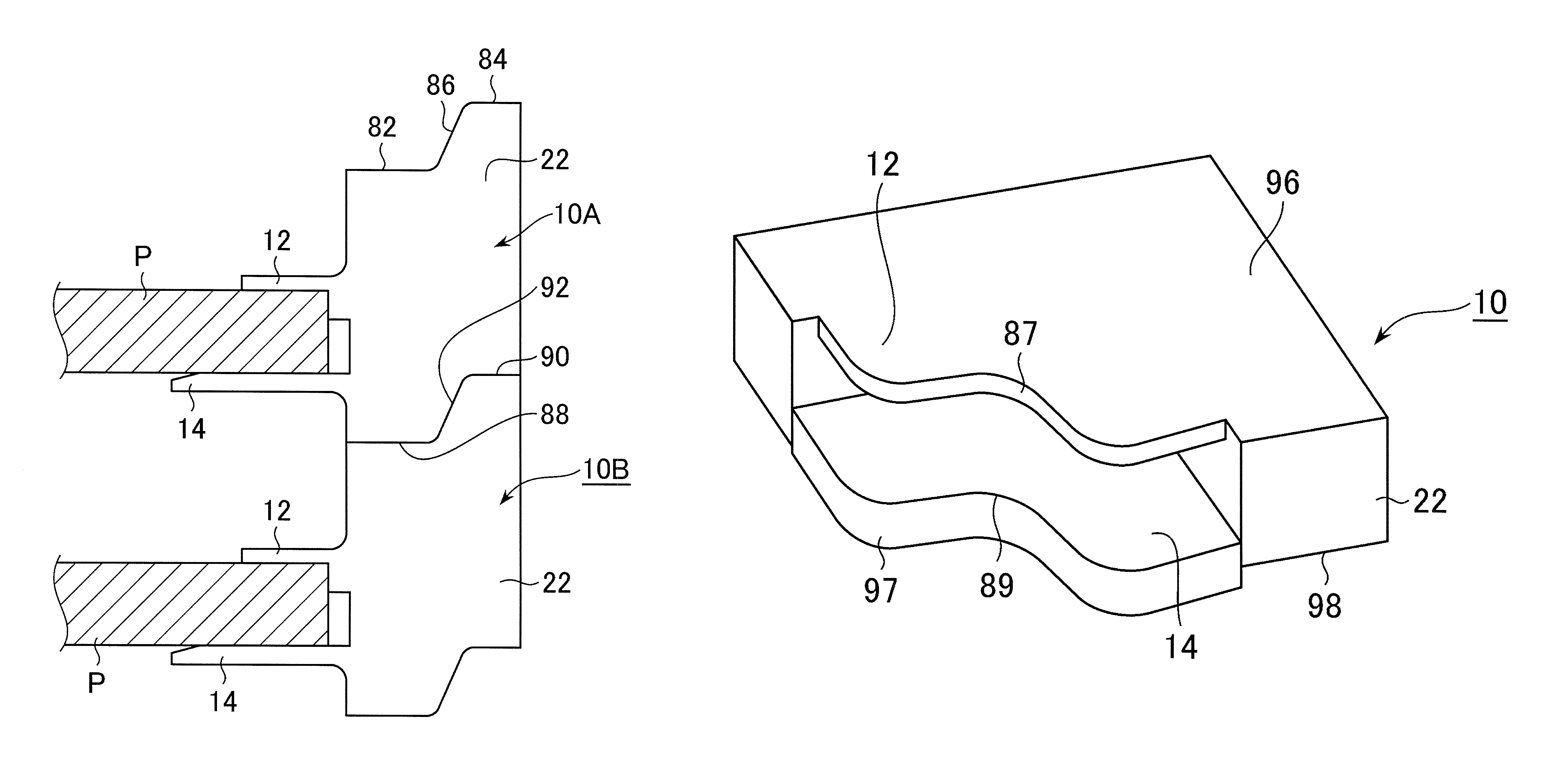
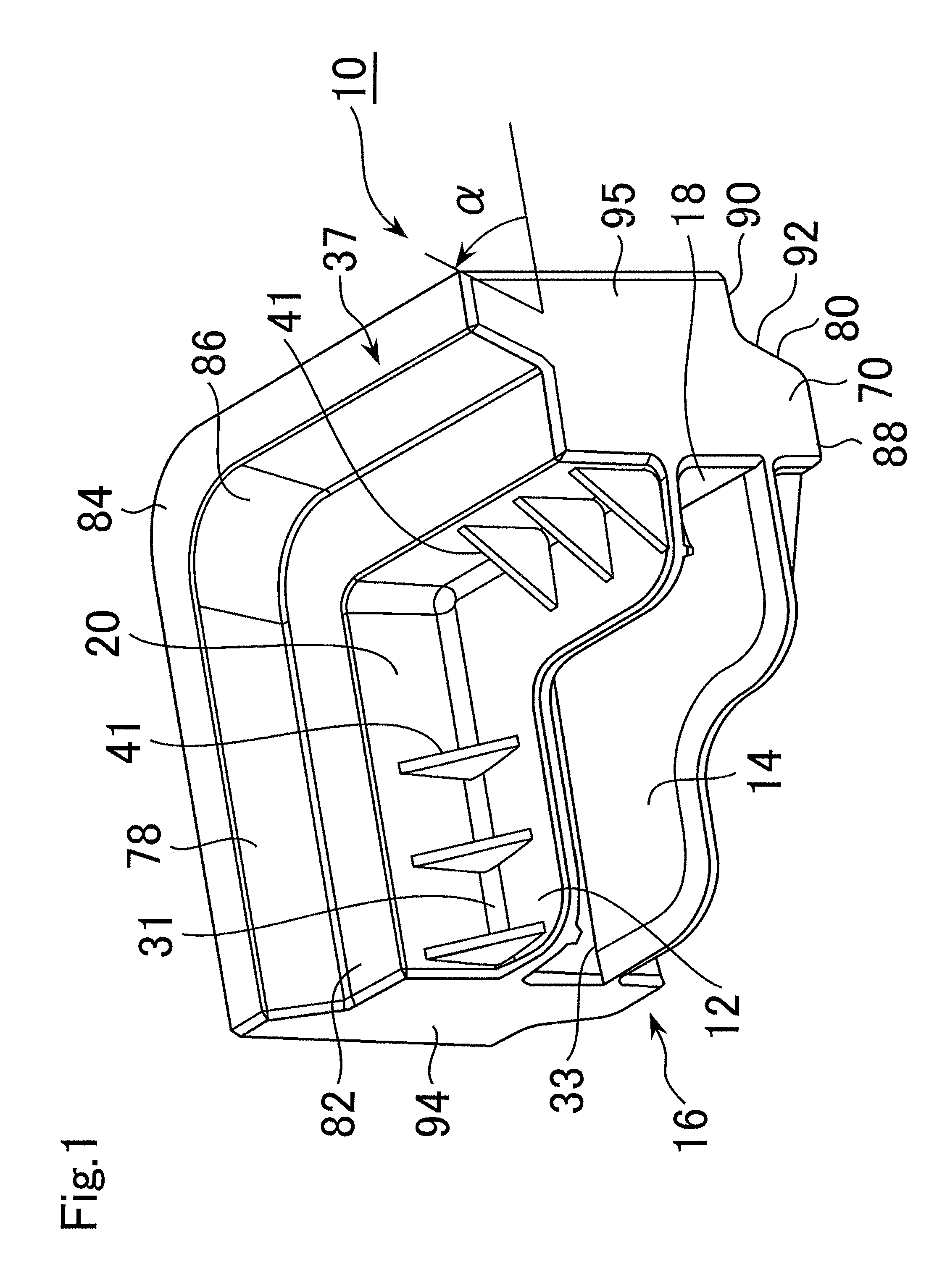
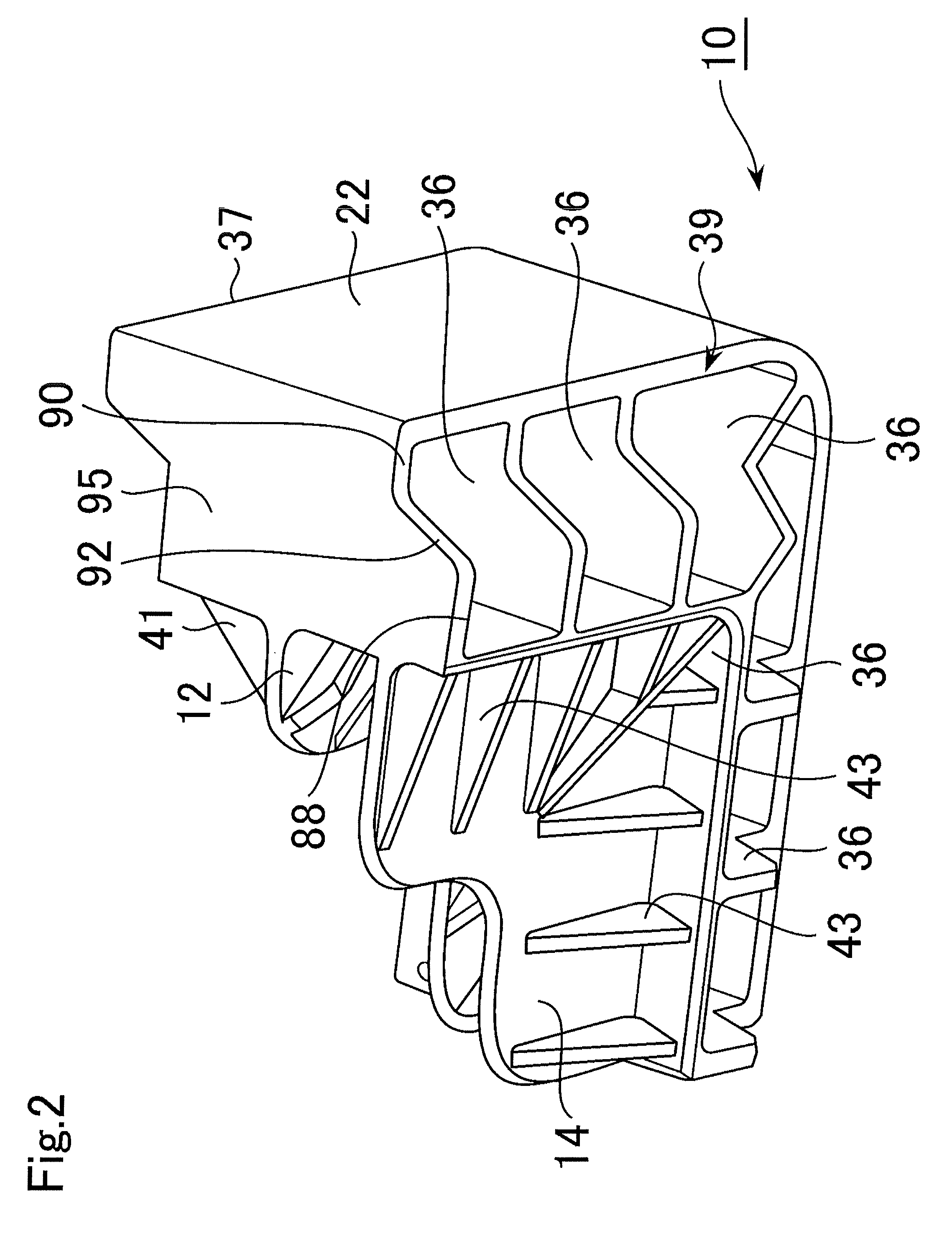
[0047]A detailed description of a module 10 according to a first embodiment of the present invention is given with reference to the drawings. In the description below, the module 10 is used for stacking rectangular solar panels P serving as an example of thin panels to be stacked.

[0048]The solar panel P includes cells that are serially connected, and resin, tempered-glass, and a metal frame for protection of these cells. The solar panel P is in the form of a thin plate. Specifically, the solar panel P has a laminated structure in which the cells made of silicone are embedded between a glass layer and a plastic layer or between glass layers. The solar panel P has a thickness of several millimeters (mm), an area of several square meters (m2), and a weight of 10 to 30 kilograms (Kg). Thus, the solar panel P is a precise and fragile structural body.

[0049]This embodiment describes a case where four modules 10 for stacking the thin panels directly support four corners of the solar panel P...


PUM


Abstract

A module for stacking thin panels and a method of stacking thin panels when a plurality of thin panels are vertically stacked in a state of being supported by the modules capable of securing an adequate load transfer area for transferring a load of the thin panels. The module for stacking the thin panels includes: a support portion for supporting the thin panel from below; a load transfer portion connected to the support portion for transferring a weight of the thin panel downward; and a drop-off preventing portion for regulating horizontal movement of the thin panel. The load transfer portion includes a load transfer surface extending outward from the support portion, the load transfer surface includes a load receiving surface provided in an upper portion of the module and a load releasing surface provided in a lower portion of the module, and the drop-off preventing portion includes a protrusion portion protruding downward from a lower portion of the module. When an upper module is stacked on a lower module such that the load releasing surface of the upper module is placed on the load receiving surface of the lower module, an outer surface of the protrusion portion of the upper module abuts on an upper inner surface of the lower module from an inner side thereof.

Description

[0001]This application claims the priority of Japanese number 2010-220491 filed Sep. 30, 2010, and Japanese number 2011-208304 filed Sep. 25, 2011, hereby incorporated by reference.BACKGROUND OF THE INVENTION[0002]1. Technical Field[0003]The present invention relates to a module for stacking thin panels and a method of stacking thin panels. The present invention particularly relates to a module for stacking a plurality of thin panels and to a method of stacking thin panels using such modules, the module allowing an adequate area for load transfer of the thin panels (load transfer area) to be secured when the plural thin panels are vertically stacked in a state of being supported by the modules. Alternatively, the present invention relates to a module for stacking a plurality of thin panels and a method of stacking thin panels using such modules, the modules allowing the plural thin panels to be efficiently and stably stacked in a vertical direction.[0004]2. Background Art[0005]Dedic...

Claims


Application Information

Patent Timeline
Patent Type & Authority Patents(United States)
IPC IPC(8): B65D85/48B65D57/00B65D81/05H01L21/673H01L31/042
CPCH01L31/0422B65D81/053B65D57/00H01L21/67346B65D85/48Y02E10/50H02S20/00B65D81/056B65D81/057B65D57/004
Inventor YOSHIDA, KOUICHIROU
Owner KYORAKU CO LTD
Why Eureka
Try Eureka