
Buckle Apparatus and Seat Belt Apparatus

a seat belt and buckle technology, applied in the field of buckle devices, can solve the problem of difficult to secure sufficient attachment strength, and achieve the effect of improving the strength of the cover, preventing the drop of the device, and improving the attachment strength

Inactive Publication Date: 2006-12-21
JOYSON SAFETY SYST JAPAN KK
View PDF10 Cites 8 Cited by
  • Summary
  • Abstract
  • Description
  • Claims
  • Application Information

AI Technical Summary

Benefits of technology

[0028] Accordingly, it is an object of the present invention to provide a buckle apparatus and a seat belt apparatus capable of improving the attachment strength of the reflector.
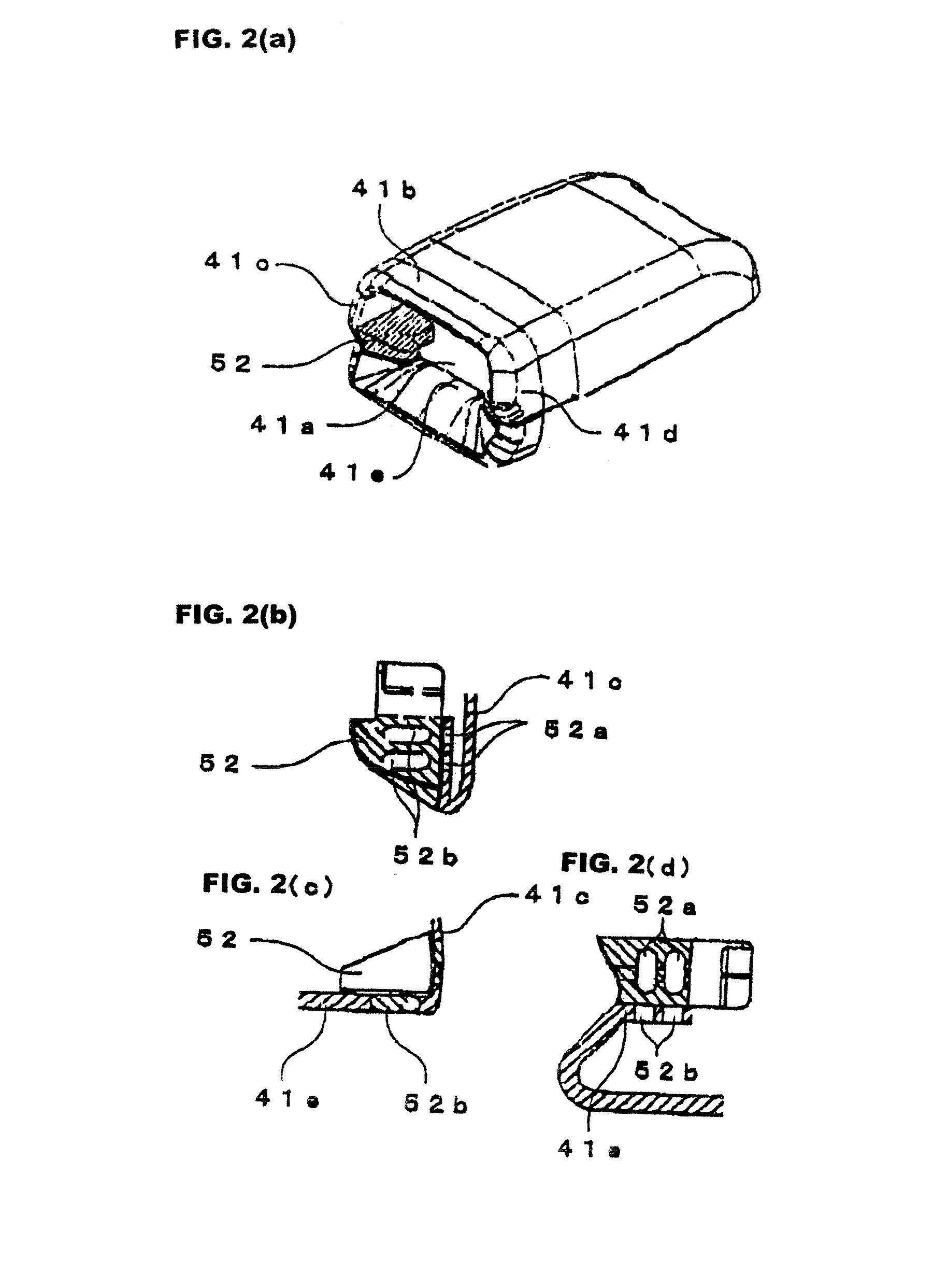
[0033] According to a buckle apparatus of the first form and a seat belt apparatus of the fourth form, a reflector is provided in a cover for the buckle apparatus by means of integral molding process and thereby attachment strength of the reflector to the cover is improved and the reflector is prevented from being dropped off. Further, because the reflector is being formed by means of integral molding process, it also functions as a strength reinforcing member for the cover, strength of the cover is improved.
[0034] According to the buckle apparatus of the second form, a part of the reflector is buried in an inner wall face of the cover that forms the insertion inlet and thereby integration of the reflector and the cover side is firmly realized and attachment strength is securely improved.
[0035] According to the buckle apparatus of the third form, a leg portion of the reflector is buried in two wall faces that construct a corner portion of the inner wall face of the cover forming the insertion inlet and thereby integration of the reflector and two wall faces of the cover is firmly realized and the attachment strength can be securely improved.

Problems solved by technology

However, in the thus constructed conventional buckle apparatus, it has been hard to secure sufficient attachment strength because the buckle apparatus has the construction in which a light guide (reflector) is merely adhered and fixed to the printed circuit board 20.

Method used


Image

  • Buckle Apparatus and Seat Belt Apparatus
  • Buckle Apparatus and Seat Belt Apparatus
  • Buckle Apparatus and Seat Belt Apparatus

Examples


Embodiment Construction

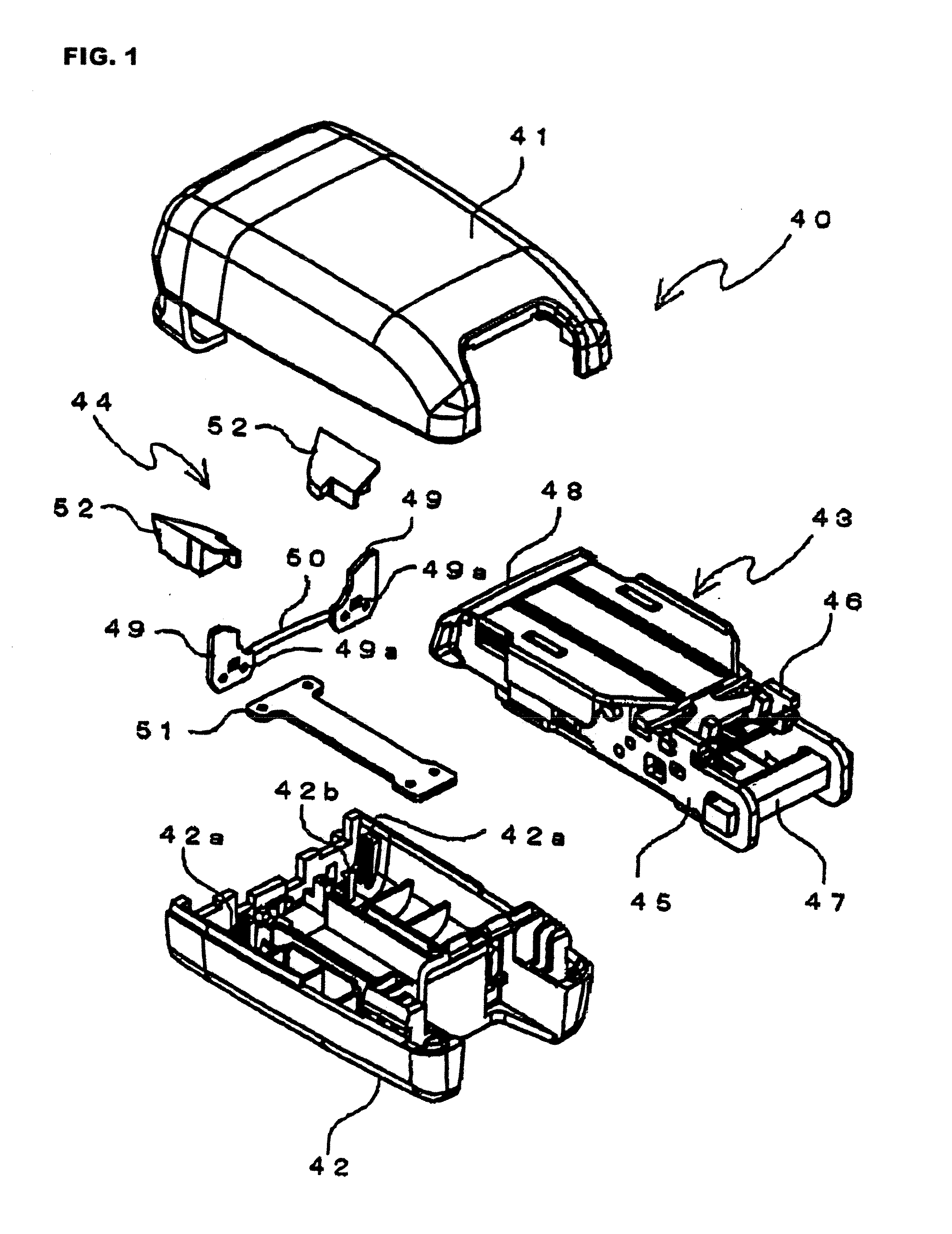
[0054] A buckle apparatus and a seat belt apparatus of the present invention will be explained on the basis of FIGS. 1 through 7.

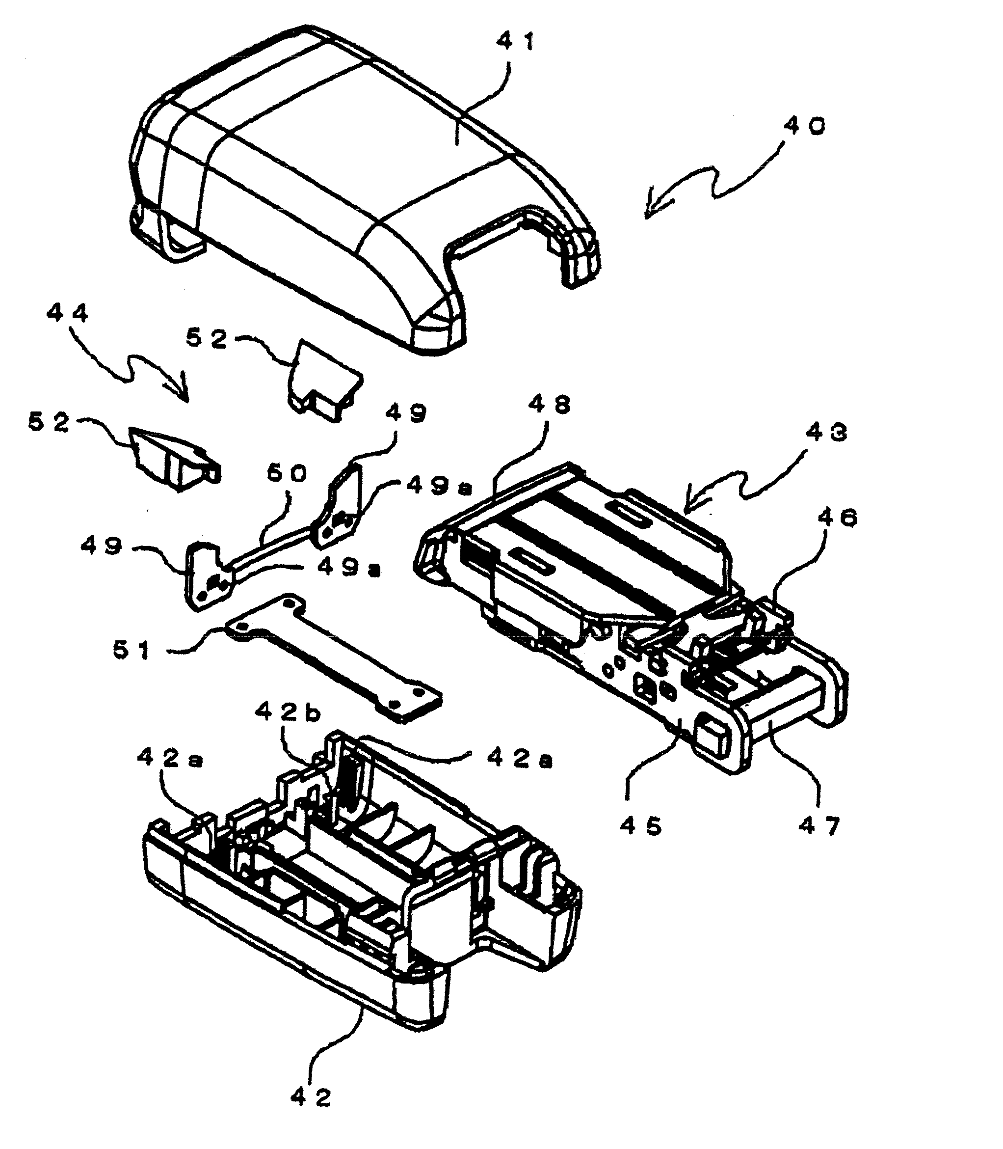
[0055]FIG. 1 is an exploded perspective view illustrating a buckle apparatus with respect to the present invention; FIG. 2(a) is a perspective view illustrating a main part of the buckle apparatus with respect to the present invention, FIG. 2(b) is a horizontal cross-section illustrating the main part of the buckle apparatus with respect to the present invention; FIG. 2(c) is a longitudinal cross-section illustrating the main part of the buckle apparatus looking from the front, and FIG. 2(d) is a longitudinal cross-section illustrating the main part of the buckle apparatus looking from the side-face direction; FIG. 3(a) is a perspective view illustrating a reflector; FIG. 3(b) is a perspective view illustrating an appearance of the reflector; FIG. 4(a) is a plan view showing a relationship between the reflector and a slimline LED light source of the buckl...


PUM


Abstract

A buckle apparatus and a seat belt apparatus are provided that are capable of improving the attachment strength of the reflector. In one form, the buckle apparatus includes an upper cover having an insertion inlet at one side, a buckle portion provided in the upper cover and engaged with a tongue of a seat belt inserted through the insertion inlet, a light source provided in the vicinity of the insertion inlet in the upper cover, a reflector for diffusing and leading illuminating light flux eradiated from the light source, which is provided in inner wall faces, that form the insertion inlet by using the reflector as a mold piece.

Description

FIELD OF THE INVENTION [0001] The present invention relates to a buckle apparatus, and more particularly to a buckle apparatus provided with an illuminating function, and to a seat belt apparatus having the buckle apparatus. BACKGROUND OF THE INVENTION [0002] Hitherto, in a seat belt apparatus for use in a motor vehicle, or the like, a buckle apparatus for fixing an end portion of webbing (belt) that keeps an occupant under restraint, or the buckle apparatus for fixing a tongue being provided at a turned back end portion of the webbing to a motor vehicle is provided. [0003] FIGS. 9(a), 9(b), and 10 illustrate an example of such a buckle apparatus in a conventional technology, in which FIG. 9(a) is a longitudinal cross-section illustrating a buckle apparatus where a tongue is in a non-latched (disengaged) state with the buckle apparatus, FIG. 9(b) is a longitudinal cross-section illustrating the buckle apparatus where the tongue is in a latched (engaged) state with the buckle apparat...

Claims


Application Information

Patent Timeline
Patent Type & Authority Applications(United States)
IPC IPC(8): F21V9/16A44B11/00B60Q3/02
CPCA44B11/2523Y10T24/45623Y10T24/40A44B11/2565
Inventor KOHAMA, SHIGERUKAWAMURA, YOSHIHIROHIROTA, AKIRA
Owner JOYSON SAFETY SYST JAPAN KK
Learn More