Bus system connecting bus bars and a method of connecting bus bars

a bus system and bus bar technology, applied in the field of bus systems, can solve the problems that the arrangement of rypinski does not offer the flexibility of design and fabrication desirable for current systems

Active Publication Date: 2015-04-14
SAI ADVANCED POWER SOLUTIONS
View PDF44 Cites 17 Cited by
  • Summary
  • Abstract
  • Description
  • Claims
  • Application Information

AI Technical Summary

Problems solved by technology

While Rypinski indicates that his construction is less expensive to manufacture than prior arrangements, the Rypinski arrangement does not offer flexibility in design and fabrication desirable for current systems.

Method used


Image

  • Bus system connecting bus bars and a method of connecting bus bars
  • Bus system connecting bus bars and a method of connecting bus bars
  • Bus system connecting bus bars and a method of connecting bus bars

Examples


Embodiment Construction

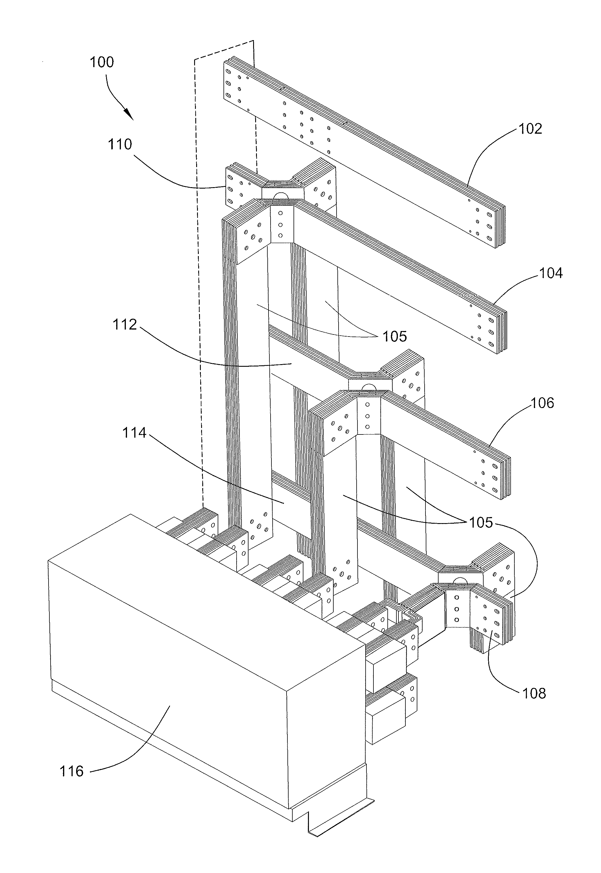
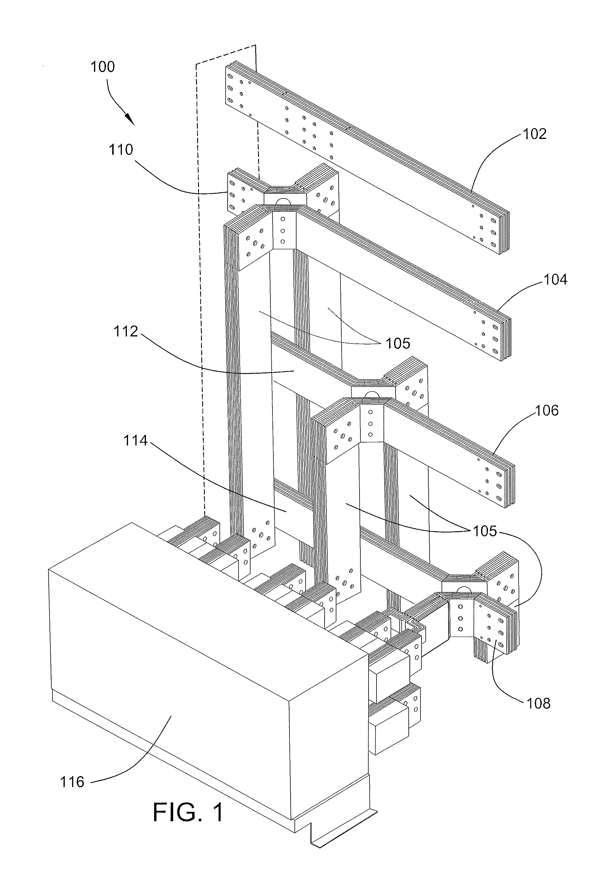
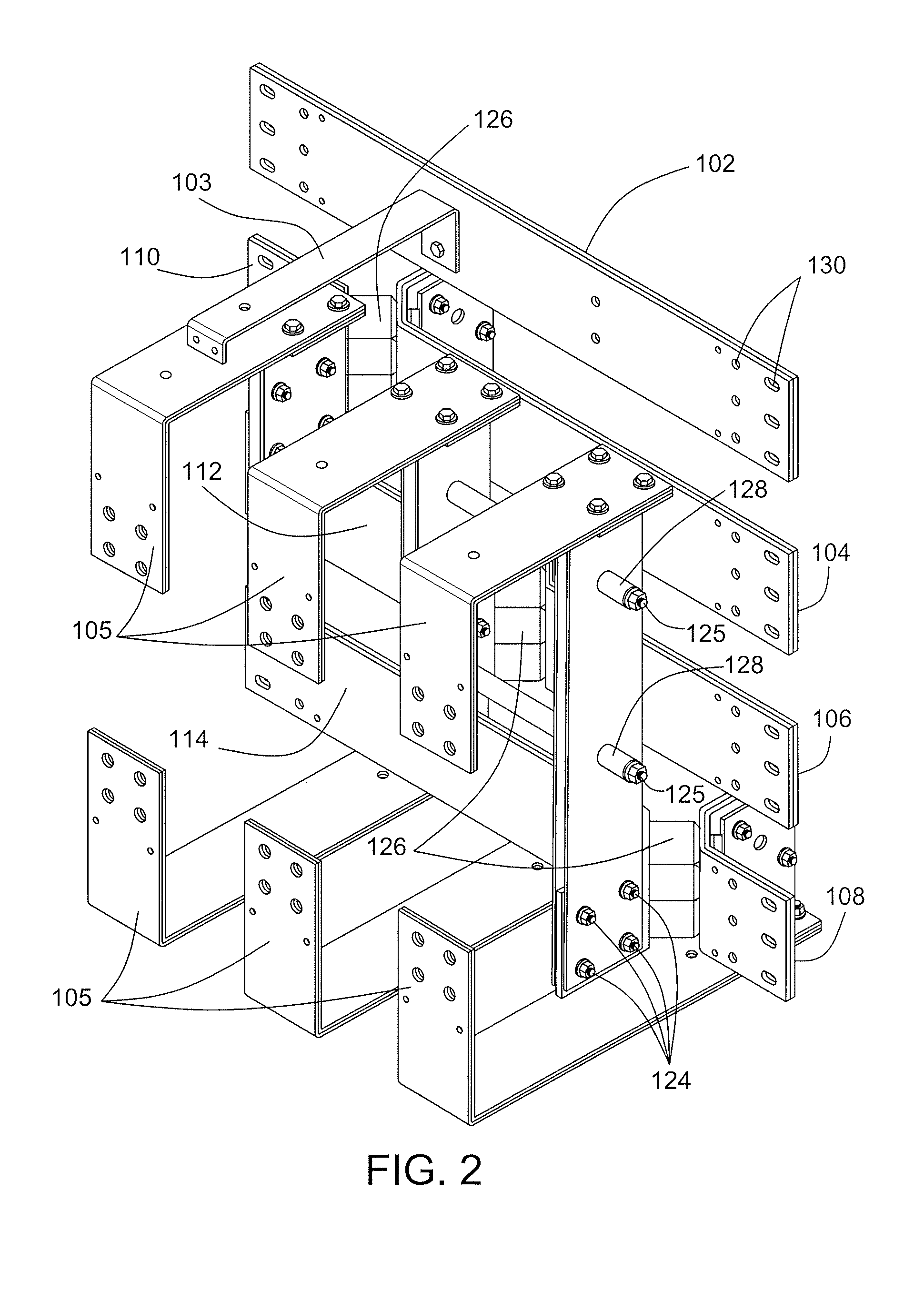
[0022]The present disclosures relates to an arrangement for connecting bus bars and a method of connecting bus bars. The bus system 100 illustrated in FIG. 1, for example, is an apparatus that allows a break in the main bus (shown in phantom), while keeping the main bus (shown in phantom) on the same centerline. The break in the main bus (shown in phantom) allows a breaker, utility current transformer, or any other device 116 to tie into the main bus (shown in phantom) by tying the three line side bus bars 110, 112, 114 and the three load side bus bars 104, 106, 108 (see FIG. 1); alternately, a bus bar extension 105 may be connected to a load or line side bus bar 104, 106, 108, 110, 112, 114; a neutral tie in bar 103 may tie into the neutral bus 102 (see FIG. 2).

[0023]In the embodiment illustrated in FIG. 1, for example, if a three phase electrical power system is used, then the system has three load side bus bars 104, 106, 108 and three line side bus bars 110, 112, 114 for carrying...


PUM

PropertyMeasurementUnit
elbow anglesaaaaaaaaaa
lengthaaaaaaaaaa
lengthaaaaaaaaaa

Abstract

According to an aspect of the disclosure, there is provided an electrical distribution bus system that includes first and second bus bars, a dielectric insulator, and at least one fastener coupling the bus bars and dielectric insulator. Each of the bus bars includes an elbow portion from which a pair of straight portions extends at elbow angles, the straight portions being disposed at right angles to each other. The dielectric insulator has a length and a width, the width being no greater than twice the length, the length extending perpendicularly between the elbow portions. The fastener couples the dielectric insulator between the bus bars, the dielectric insulator electrically insulating the first and second bus bar from one another.

Description

FIELD OF THE DISCLOSURE[0001]This disclosure relates to bus system and, more particularly, to a bus system which allows for a break in the main bus to facilitate attachment of a device, while keeping the main bus on the same centerline.BACKGROUND OF THE DISCLOSURE[0002]Bus bars are utilized in electrical power distribution systems to conduct electricity, typically from an electrical panel board. To allow heat to dissipate relatively efficiently, bus bars are typically either flat strips or hollow tubes to provide a relatively high surface area to cross-sectional area ratio. Bus bars may be supported on insulators within a system. In U.S. Pat. No. 2,606,957 to Rypinski, sections of bus bars are completely surrounded with insulation. While Rypinski indicates that his construction is less expensive to manufacture than prior arrangements, the Rypinski arrangement does not offer flexibility in design and fabrication desirable for current systems.SUMMARY OF THE DISCLOSURE[0003]According t...

Claims


Application Information

Patent Timeline
Patent Type & Authority Patents(United States)
IPC IPC(8): H02G5/00H01B5/02H02G15/08H02G3/06H01R4/00H02B1/20H01R4/60H02B1/21H02G5/02
CPCH02G5/02H02B1/21Y10T29/49117
Inventor MANHART, JAMES S.RYAN, JOHN F.
Owner SAI ADVANCED POWER SOLUTIONS
Why Eureka
Try Eureka