Surgical reaming instrument for shaping a bone cavity

a bone cavity and surgical technology, applied in the field of surgical instruments, can solve the problems of loss of native bone near the joint being replaced, general inability to use the joint, and often necessary revision procedures

Active Publication Date: 2015-04-21
HOWMEDICA OSTEONICS CORP
View PDF119 Cites 26 Cited by
  • Summary
  • Abstract
  • Description
  • Claims
  • Application Information

AI Technical Summary

Problems solved by technology

Once native bone is resected from a joint, it generally can no longer be used in the joint.
When prosthetic components fail for any one of a variety of reasons, a revision procedure is often necessary.
An issue generally encountered by surgeons replacing joints during a revision procedure is the loss of native bone near the joint being replaced.
Defects in a bone adjacent a joint, such as the hip or knee, may occur due to wear and arthritis of the joint, congenital deformity, and following the removal of a failed prosthetic component.
When the failed prosthetic component or components are removed from the joint during a revision procedure, it is common for there to have been further native bone loss in the area adjacent the original implant position of the prosthetic component or components.
This bone loss is typically due to movement of the component or components after implantation or even degeneration or further degeneration of the bone, which can form bone voids that have unpredictable and non-uniform shapes.
Problems with these methods include that reaming is performed on the IM axis only, so that void areas at a distance from the IM axis, which commonly occur, can only be resected using manual methods.
Moreover, broaching generally has at least two problems.
First, a manual operation can be time consuming, particularly in cases of sclerotic bone, which exposes the patient to an increased risk of infection and a longer recovery.
Second, in the case of large bone voids, broaching generally needs to be performed in a multi-step process because attempting to remove high volumes of bone in a single broaching step generally requires high impact forces to the bone.
Also, freehand bone removal, either powered or unpowered, such as by burr or rongeur, often does not produce accurate cavity shapes to receive predefined prosthetic components.
A typical result is that areas remain where the outer walls of the MRD do not contact the cavity, which may lead to undesirable stress distribution and possible loss of bone regrowth.
Also typical is the time consuming requirement of iterative bone removal, with multiple checks against the MRD, to obtain a correct fit.

Method used


Image

  • Surgical reaming instrument for shaping a bone cavity
  • Surgical reaming instrument for shaping a bone cavity
  • Surgical reaming instrument for shaping a bone cavity

Examples


Embodiment Construction

[0075]As used herein, when referring to the surgical reaming instrument of the present invention, the term “proximal” means closer to the surgeon or in a direction toward the surgeon and the term “distal” means more distant from the surgeon or in a direction away from the surgeon. The term “anterior” means towards the front part of the body or the face and the term “posterior” means towards the back of the body. The term “medial” means toward the midline of the body and the term “lateral” means away from the midline of the body.

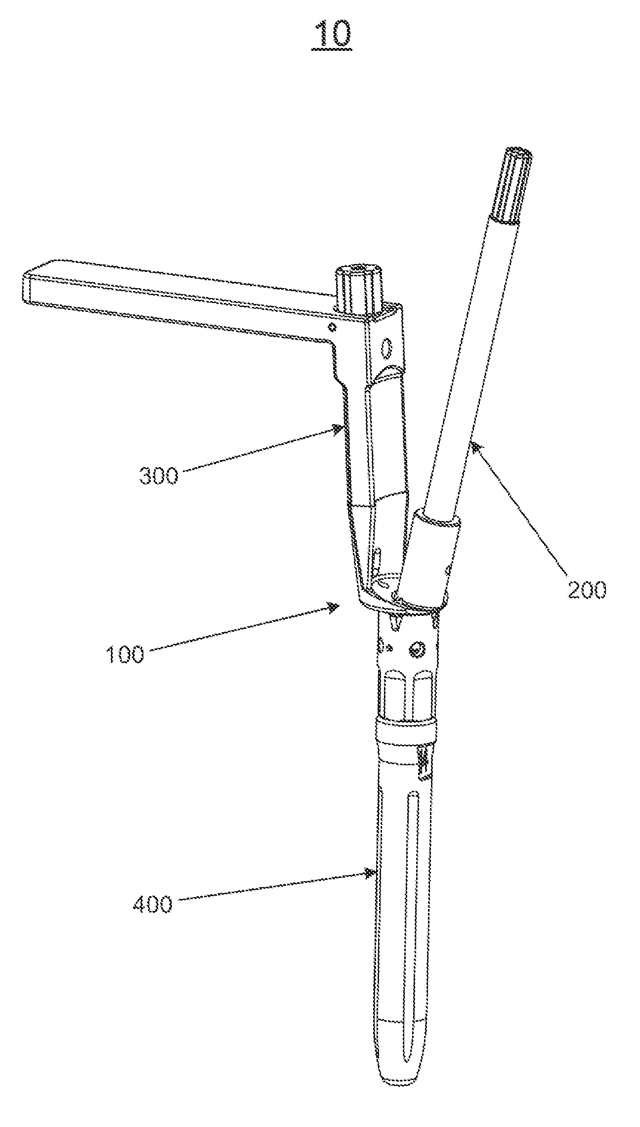
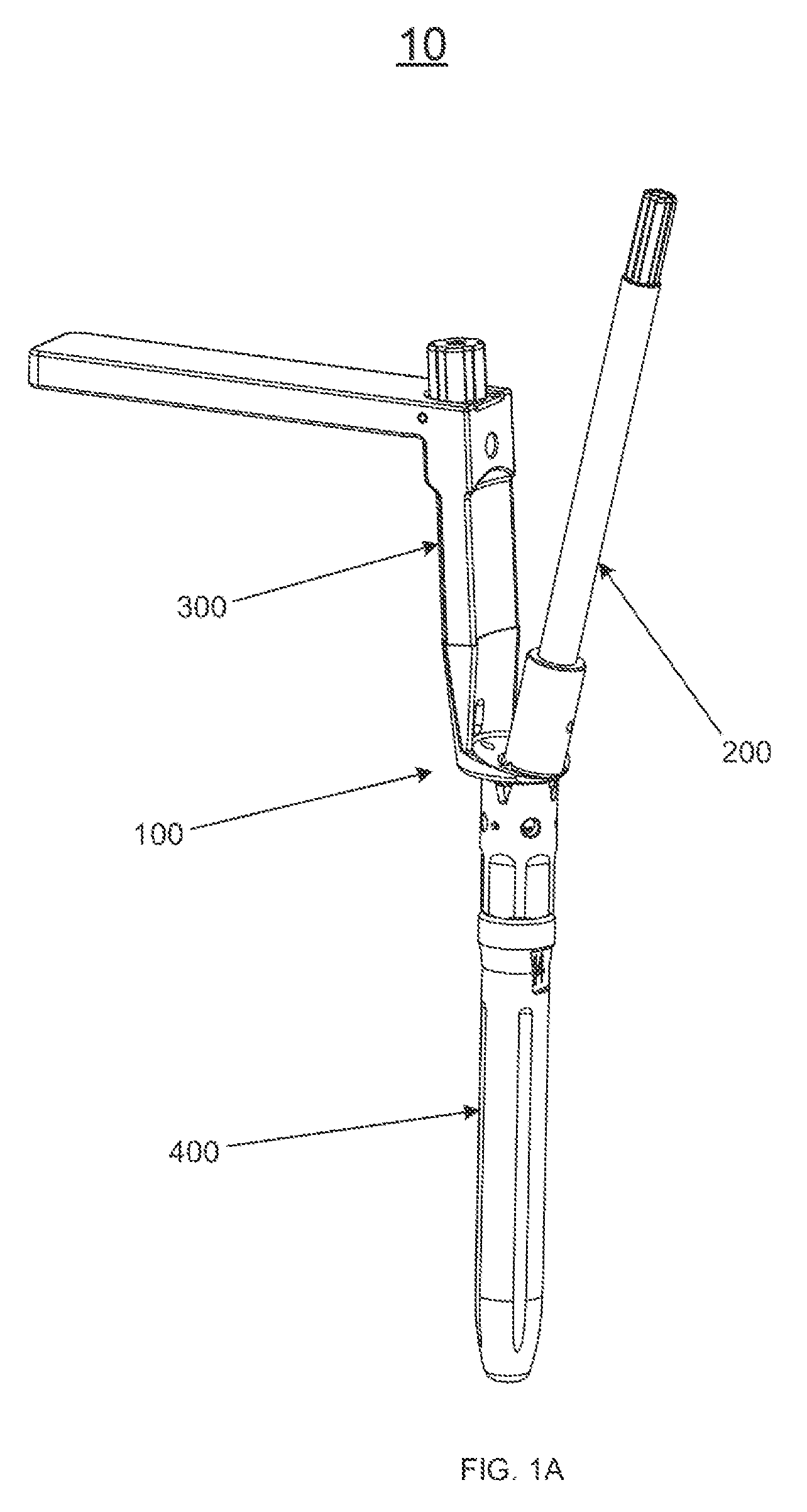
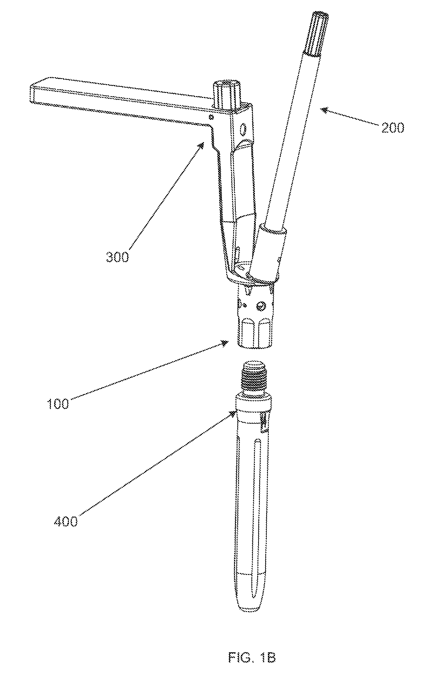
[0076]FIG. 1A shows a surgical reaming instrument 10. The surgical reaming instrument 10 generally includes a reaming guide assembly 100, a guide tube assembly 200, a handle assembly 300, and a trial stem 400, each of which will be described in further detail below. FIG. 1B shows the surgical reaming instrument 10 with the trial stem 400 removed from the reaming guide assembly 100.

[0077]FIGS. 2A-C show the reaming guide assembly 100 in detail. FIG. 2A shows a...


PUM


Abstract

Disclosed herein are systems and methods for shaping bone voids during revision procedures of total knee replacements. The systems disclosed herein generally include a cannulated reamer assembly, a reaming guide assembly, a guide tube assembly, a trial stem assembly, and an optional insertion / removal tool. Metaphyseal reconstruction devices can be used to fill the bone voids in conjunction with the systems and methods disclosed herein.

Description

CROSS-REFERENCE TO RELATED APPLICATION[0001]This application claims the benefit of the filing date of U.S. Provisional Patent Application No. 61 / 568,808, filed Dec. 9, 2011, the disclosure of which is hereby incorporated herein by reference.FIELD OF THE INVENTION[0002]The present invention relates to surgical instruments for preparing a bone to receive a joint prosthesis system, and in particular relates to fully guided surgical reaming instruments for use in total knee replacement revision procedures.BACKGROUND OF THE INVENTION[0003]Joint replacement surgery is a common orthopedic procedure for joint such as the shoulder, hip, knee, ankle and wrist. Prior to implanting prosthetic components in a joint of a patient, a surgeon generally has to resect at least a portion of the patient's native bone in order to create a recess or cavity for receiving at least a portion of the prosthetic components being implanted. During the process of resecting bone, a surgeon generally only resects t...

Claims


Application Information

Patent Timeline
Patent Type & Authority Patents(United States)
IPC IPC(8): A61B17/16A61F2/38A61B17/17A61F2/30A61F2/46
CPCA61B17/16A61B17/17A61B17/1675A61B17/1764A61F2/4684A61F2/3859A61F2/389A61B17/162A61F2/30734A61B17/1637A61B17/1717
Inventor PRIMIANO, STEVENSERVIDIO, DAMON J.MOORADIAN, MARKARNETT, JEFFERY
Owner HOWMEDICA OSTEONICS CORP
Why Eureka
Try Eureka