Knee prosthesis

a total knee and prosthesis technology, applied in knee joints, ligaments, medical science, etc., can solve the problems of less than perfect total knee prosthesis, more frequent revision surgery, wear and tear of the prosthesis, etc., to prolong the useful life in situ, reduce wear and tear, and effectively replicate the natural knee kinematics

Inactive Publication Date: 2014-05-08
SEVIKA HLDG
View PDF0 Cites 19 Cited by
  • Summary
  • Abstract
  • Description
  • Claims
  • Application Information

AI Technical Summary

Benefits of technology

[0013]The present invention provides an improved knee prosthesis for total knee arthroplasty. The prosthesis may have a number of advantages, such as but not limited to effectively replicating natural knee kinematics and reducing wear and tear of the prosthesis thus prolonging its useful life in situ. In various embodiments, the prosthesis may be provided as a system including multiple components, such as a femoral component, tibial component, meniscal component and patellar component, or some subset of those components.
[0015]The meniscal component may include an inferior side for mating with the tibial component, a superior side for mating with the femoral component, an anterior side, a posterior side, a lateral side and a medial side. The meniscal component may also include: an anterior articulating surface on the superior side for mating with the anterior joint surface of the femoral component; a posterior lateral articulating surface on the superior side for mating with the lateral condyle of the femoral component, the posterior lateral articulating surface having an approximately horizontal profile in an anterior-to-posterior direction; a posterior medial articulating surface on the superior side for mating with the medial condyle of the femoral component, the posterior medial articulating surface having an upward sloping profile in an anterior-to-posterior direction; medial and lateral projections on the superior side for mating with the medial and lateral grooves of the femoral component; a post extending from the superior surface and configured to mate with the intercondylar opening of the femoral component, wherein a central axis of the post is disposed closer to the posterior side than to the anterior side of the meniscal component; and an anterior cutout on the anterior side of the superior surface to prevent injury to a patellar tendon.
[0019]In another aspect of the present invention, a knee prosthesis for use in a total knee replacement surgical procedure may include a femoral component as described above and a meniscal component. The meniscal component may be largely as describe above but may include a bone attachment side for attaching to a cut proximal end of a tibia and a superior side for mating with the femoral component, thus eliminating the need for a separate tibial component. In some embodiments, the meniscal component may be made entirely of a polymer such as ultra-high-molecular-weight polyethylene (UHMWPE). As in previously described embodiments, the prosthesis may optionally also include a patellar component having a cutout portion on an inferior edge.

Problems solved by technology

Many different total knee implants (or “knee prostheses”) have been developed in pursuit of these goals, but no total knee prosthesis is perfect.
Other prostheses may provide certain kinematic advantages but may wear out more easily, thus requiring revision surgery more frequently.
In an arthritic knee, protective cartilage at the point of articulation of the femur with the tibia has been worn away, which causes significant pain and discomfort.
The goals of freedom of motion and stability can conflict with one another, since creating a more stable knee joint often means reducing freedom of motion.
For example, most currently available prostheses compromise either knee joint stability or natural, full range of motion to an extent that is suboptimal for a patient.
Additionally, most prostheses wear out more quickly than would be ideal, often in predictable wear patterns.
Another limitation with conventional posterior cruciate substituting knee designs is that they require excess removal of bone for implantation.
Excessive bone removal can lead to intraoperative fractures due to the stress concentration created by cutting out bone to accommodate the box of the design.
Bone removal is also disadvantageous, because, in the event of revision surgery, the more bone available, the easier the revision surgery will be.

Method used


Image

  • Knee prosthesis
  • Knee prosthesis
  • Knee prosthesis

Examples


Embodiment Construction

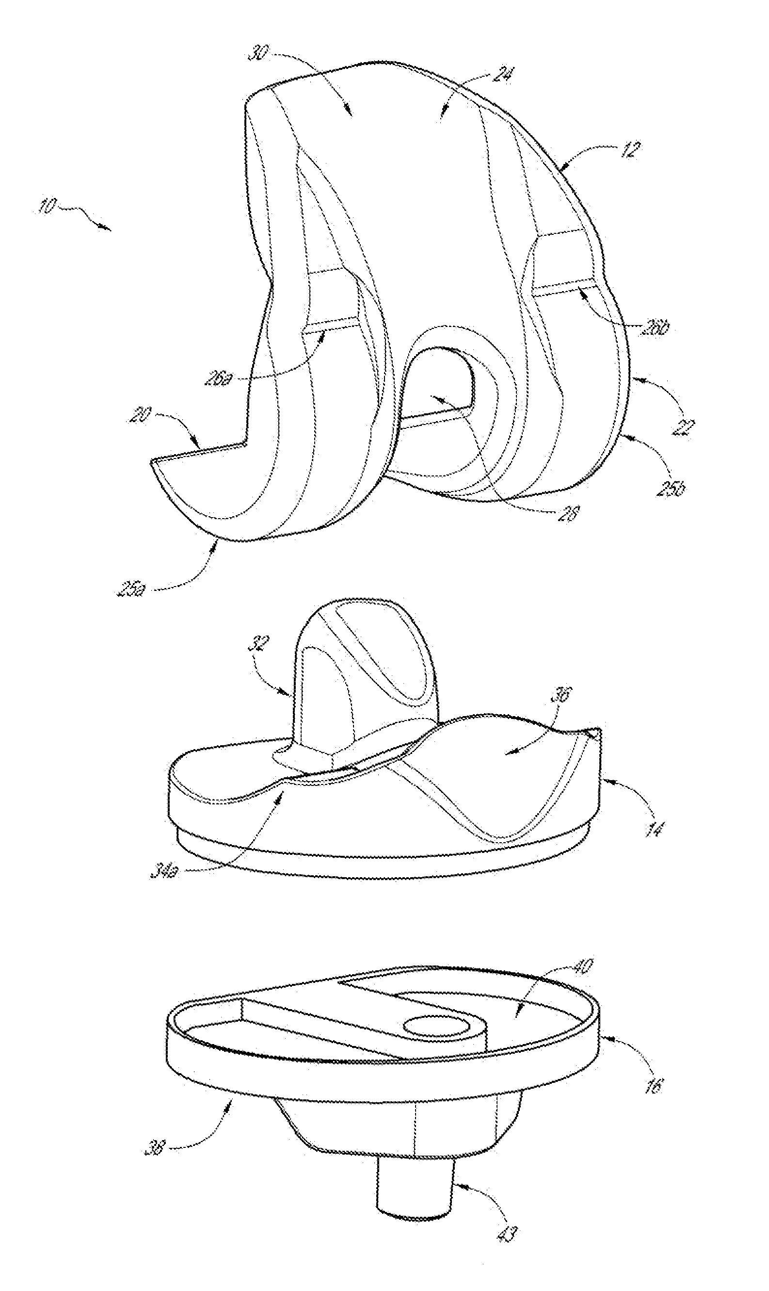
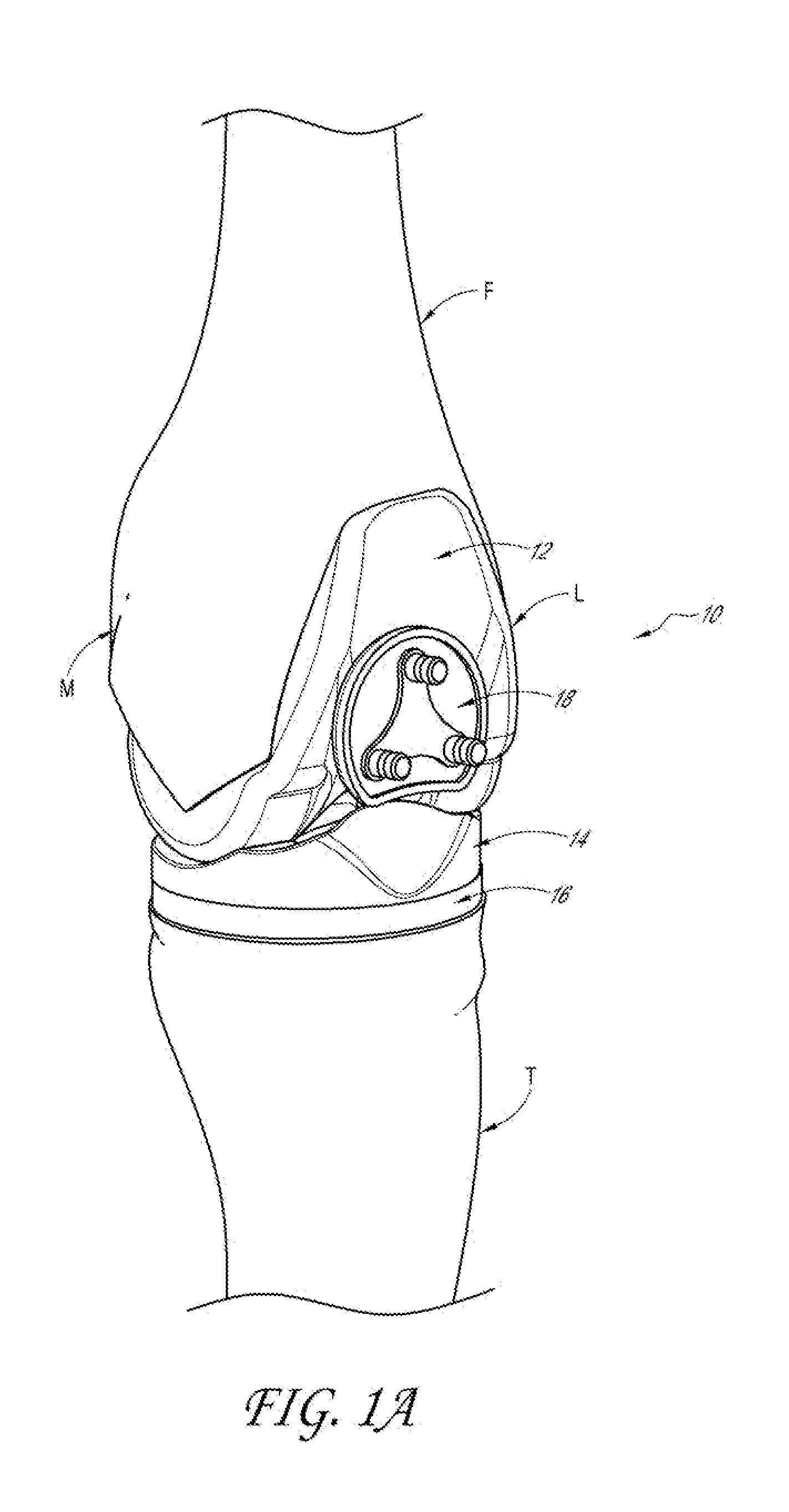
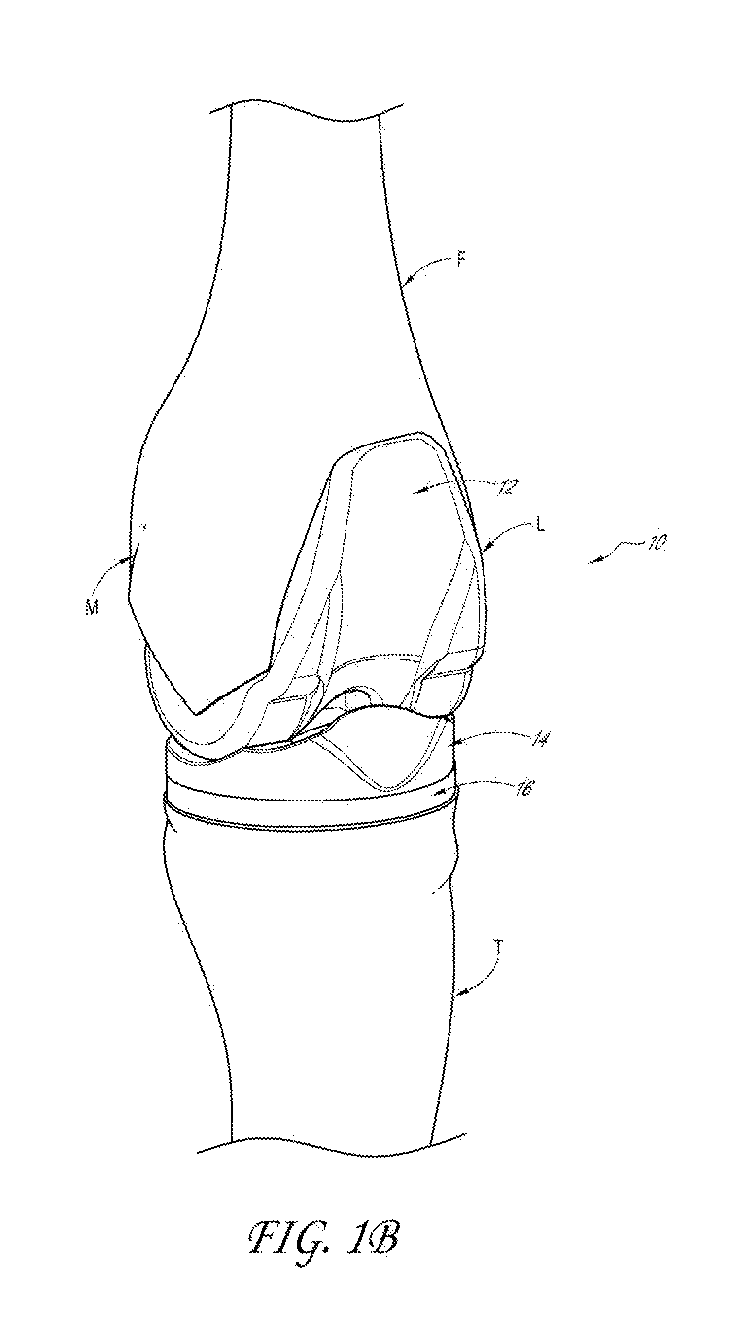
[0043]Referring to FIGS. 1A-1D, in one embodiment, a knee prosthesis system 10 may include a femoral component 12, a meniscal component 14, a tibial component 16, and optionally a patellar component 18. In FIG. 1A, knee prosthesis system 10 is shown with patellar component 18, while in FIGS. 1B-1D, it is shown without patellar component 18. In other embodiments, system 10 may be provided without tibial component 16, for example when meniscal component 14 attaches directly to the cut tibia (not shown). In yet other embodiments, multiple sizes of one or more components may be provided as part of system 10, for example as a kit or suite of operating room tools so that a surgeon can select a desired size of each component or set of components. Generally, therefore, system 10 may include any two or more components of a knee prosthesis as described herein. Although system 10 is typically described below as including femoral 12, meniscal 14 and tibial 16 components, with an optional patell...


PUM


Abstract

A knee prosthesis for use in a total knee replacement surgical procedure may include a femoral component, a tibial component and a meniscal component. Optionally, the prosthesis may also include a patellar component. The femoral component may include a bone attachment side and a joint facing side, the latter including an anterior joint surface, a posterior joint surface having a cross-sectional shape defining a portion of a cylinder, and medial and lateral grooves between the anterior and posterior joint surfaces. The meniscal component may include a number of features designed to mate with the femoral component to provide relatively natural movement and range of motion about the knee joint as well as stability and resistance to wear and tear.

Description

BACKGROUND OF THE INVENTION[0001]1. Field of the Invention[0002]The invention is related to surgical devices for total knee replacement surgery. More specifically, the invention is related to a knee prosthesis for total knee replacement surgery.[0003]2. Description of the Related Art[0004]Approximately 581,000 total knee replacement surgeries (also referred to as total knee arthroplasty (“TKA”)) are performed annually in the U.S. for the treatment of chronic knee pain and dysfunction. As the U.S. and world populations become older and more obese and knee joints endure greater wear and tear from increased loads and years of stress, TKA becomes a more and more commonly performed surgical procedure. The goals of TKA are to provide the patient with a knee joint that is pain free, moves naturally through a full range of motion, provides stability during motion and rest, and lasts as long as possible. Many different total knee implants (or “knee prostheses”) have been developed in pursuit...

Claims


Application Information

Patent Timeline
Patent Type & Authority Applications(United States)
IPC IPC(8): A61F2/38
CPCA61F2/3872A61F2/3877A61F2/3886A61F2002/30884A61F2002/30934
Inventor HOWARD, MICHAEL J.JOHANNABER, KENNETH D.
Owner SEVIKA HLDG
Why Eureka
Try Eureka