Systems and methods for preparing bone voids to receive a prosthesis

a technology for preparing a bone to receive a prosthesis, applied in the field of surgical instruments for preparing a bone to receive a joint prosthesis, can solve the problems of reducing the ability of the patient to fully recover, and affecting the healing effect of the patient,

Active Publication Date: 2015-10-06
HOWMEDICA OSTEONICS CORP
View PDF121 Cites 17 Cited by
  • Summary
  • Abstract
  • Description
  • Claims
  • Application Information

AI Technical Summary

Problems solved by technology

When prosthetic components fail for any one of a variety of reasons, a revision procedure is often necessary.
Although defects in a bone adjacent a joint, such as the hip or knee, may occur naturally due to wear and arthritis of the joint and congenital deformities, the removal of a failed prosthetic component also creates an issue with maintaining native bone.
Specifically, when prosthetic components are removed from the joint during a revision procedure, it is common for there to have been further native bone loss in the area adjacent the original implant position of the prosthetic components due to movement of the components after implantation or even further degeneration of the bone.
Also, freehand bone removal, either powered or unpowered, such as by burr or rongeur, often does not produce accurate cavity shapes to receive prosthetic components having predefined configurations.
A typical result of the above mentioned methods is that areas remain where the outer walls of the MRD do not contact the cavity, which may lead to undesirable stress distribution and possible loss of bone regrowth.
Also typical is the time consuming requirement of iterative bone removal, with multiple checks against the MRD, to obtain a correct fit.

Method used


Image

  • Systems and methods for preparing bone voids to receive a prosthesis
  • Systems and methods for preparing bone voids to receive a prosthesis
  • Systems and methods for preparing bone voids to receive a prosthesis

Examples


Embodiment Construction

[0080]As used herein, when referring to the surgical reaming instruments of the present invention, the term “proximal” means closer to the surgeon or in a direction toward the surgeon and the term “distal” means more distant from the surgeon or in a direction away from the surgeon. The term “anterior” means towards the front part of the body or the face and the term “posterior” means towards the back of the body. The term “medial” means toward the midline of the body and the term “lateral” means away from the midline of the body.

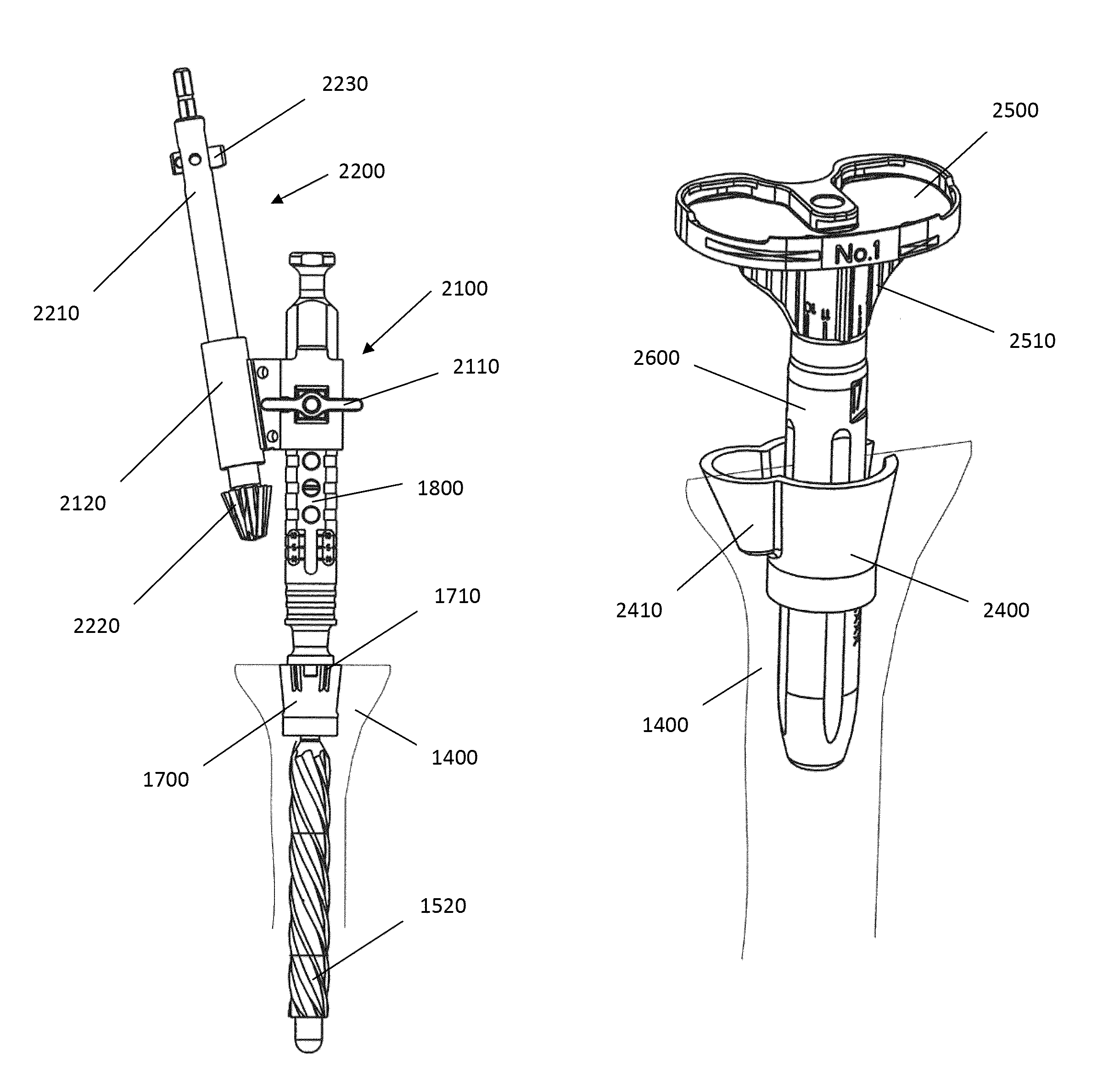
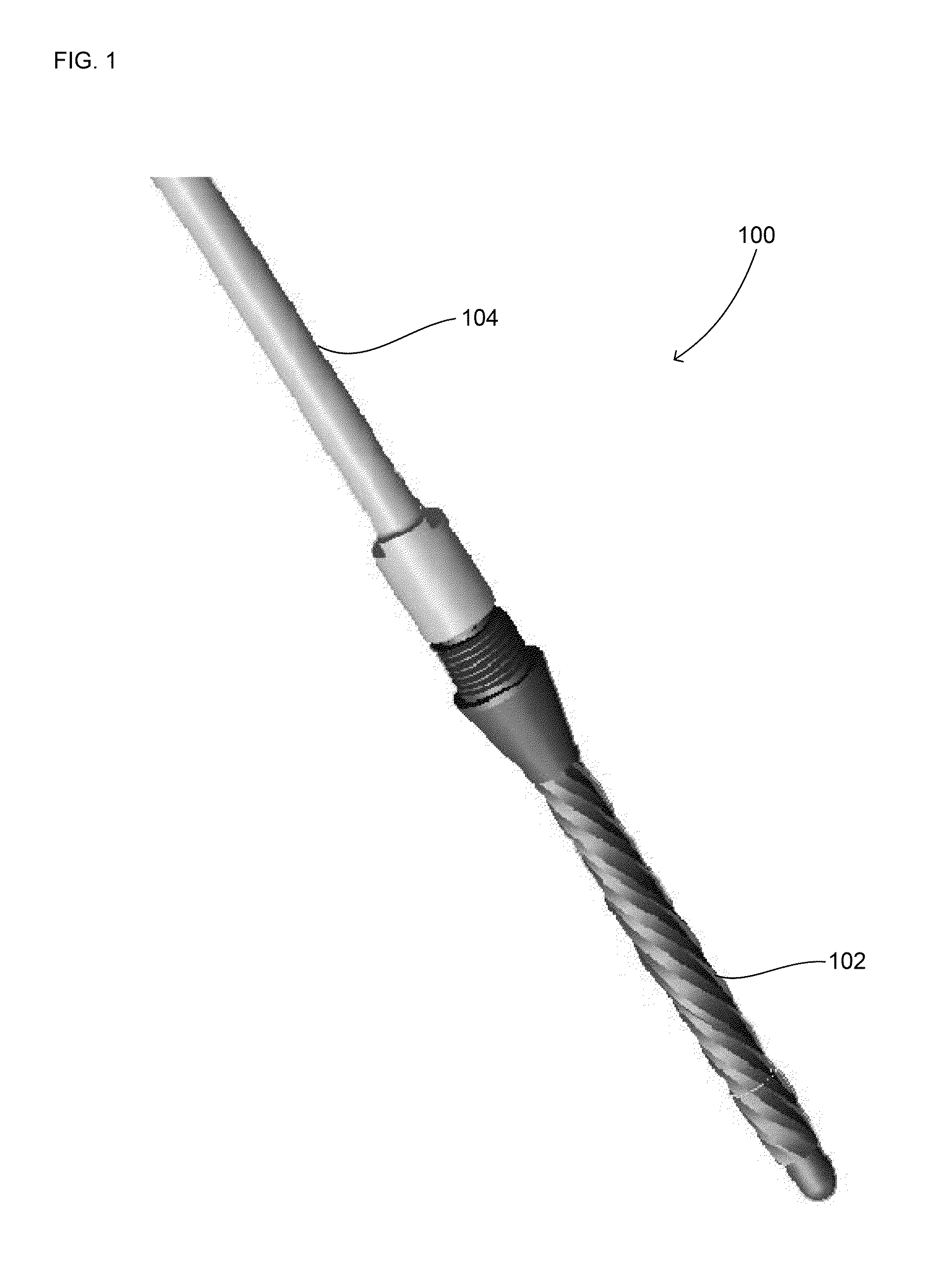
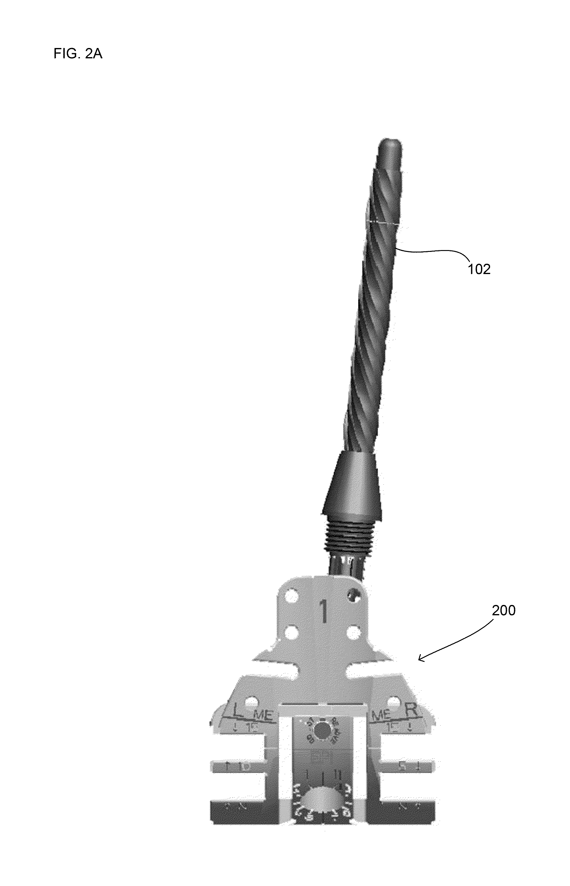
[0081]FIG. 1 illustrates a side view of a two part reamer 100. The two part reamer consists of an IM reamer 102 and inline driver 104. In the assembled position as shown, longitudinal axes of the IM reamer 102 and inline driver 104 are coaxial. In a revision procedure, the initial step after removing the prosthesis located in the bone is to ream the bone generally along a longitudinal axis thereof. In total knee revision procedures, for example, the bone is ...


PUM


Abstract

Systems and methods for shaping and filling offset bone voids during revision procedures of total knee replacements are disclosed. The systems disclosed herein generally include an intramedullary reamer, an offset driver, a cylindrical reaming tool, an offset reaming guide, and a conical reamer. An alternate embodiment of the system may also generally include an IM reamer, an offset driver, an offset broaching tool, and a second stage broaching tool. Yet another embodiment may generally include an elongate IM reamer, a cone reamer, a reamer guide shaft, a cone trial, a sizing template, a template guide, an offset lobe reamer, and offset lobe reamer retainer. Metaphyseal reconstruction devices and void filling cones can be used to fill the bone voids in conjunction with the systems and methods disclosed herein.

Description

CROSS-REFERENCE TO RELATED APPLICATION[0001]The present application claims the benefit of the filing date of U.S. Provisional Application No. 61 / 581,736, filed Dec. 30, 2011, the disclosure of which is hereby incorporated herein by reference.FIELD OF THE INVENTION[0002]The present invention relates to surgical instruments for preparing a bone to receive a joint prosthesis system, and in particular to guided surgical reaming instruments and bone void fillers for use in total knee replacement revision procedures.BACKGROUND OF THE INVENTION[0003]Joint replacement surgery is a common orthopedic procedure for joints such as the shoulder, hip, knee, ankle and wrist. Prior to implanting prosthetic components in a joint of a patient, a surgeon generally has to resect at least a portion of the patient's native bone in order to create a platform and / or recess or cavity for receiving at least a portion of the prosthetic components being implanted. During the process of resecting bone, a surgeo...

Claims


Application Information

Patent Timeline
Patent Type & Authority Patents(United States)
IPC IPC(8): A61B17/16A61B17/17A61F2/38A61F2/30
CPCA61B17/164A61B17/1668A61B17/1675A61B17/175A61B17/1717A61B17/1764A61F2/38A61F2/389A61F2/3859A61B17/1615A61F2002/30604A61F2002/30736A61F2002/30884A61B17/1662A61B17/1739
Inventor SERVIDIO, DAMON J.COLLAZO, CARLOS E.SIVADAS, SUJIT
Owner HOWMEDICA OSTEONICS CORP
Why Eureka
Try Eureka