Universal stop tube

a technology of universal stop tube and strut assembly, which is applied in the direction of shock absorbers, wing accessories, manufacturing tools, etc., can solve the problems of not being able to automatically lock open and release prior art devices, and prior art devices are often rather clumsy to manipulate, so as to facilitate the disengagement of the locking tube

Active Publication Date: 2015-05-19
BARNES GROUP
View PDF9 Cites 9 Cited by
  • Summary
  • Abstract
  • Description
  • Claims
  • Application Information

AI Technical Summary

Benefits of technology

[0019]In accordance with one non-limiting aspect of the present invention, a universal stop tube is provided that can be retrofitted to most common spring-loaded cylinder or strut assemblies and which provides the force to automatically activate and hold open the strut assembly. The universal stop tube apparatus is generally of a durable and reliable construction and can be easily and efficiently manufactured. The apparatus is designed so that is can be retrofitted to most common existing storm or screen door closing devices with minimal effort.
[0021]In accordance with yet another non-limiting aspect of the present invention, the strut includes a flexible clip which facilitates disengagement of the locking tube and respective unassisted self-closing of the strut assembly.
[0027]It is another non-limiting object of the present invention to provide a device for maintaining a strut assembly in a particular self-actuated, opened, and locked orientation and facilitating closure subsequent thereto.
[0028]It is still another non-limiting object of the present invention to provide a device that attaches directly to a generic closing cylinder or strut assembly and that allows a person to secure a strut in place simply by opening the strut to a predetermined extent.
[0030]It is still yet another non-limiting object of the present invention to provide a device that can be retrofitted to most common spring-loaded cylinder or strut assemblies and which provides the force to automatically activate and hold open the strut assembly.
[0032]It is still another non-limiting object of the present invention to provide a device that includes a flexible clip which facilitates disengagement of the locking tube and respective unassisted self-closing of the strut assembly.

Problems solved by technology

One of the only complaints in the use of such door closers is the ease (i.e. lack thereof) with which a person can set the door closer to stay open or conversely, the ease (i.e. lack thereof) with which a door being held open can be released.
There are various disadvantages inherent in all of these prior art devices.
To Applicant's knowledge, none of the prior art devices can be automatically locked open and released by simply moving the door without manual intervention.
The prior art devices are often rather clumsy to manipulate when attempting to set or release a latch.
Other disadvantages of the prior art devices are that they are rather complicated, hard to maintain, and expensive to produce.

Method used


Image

  • Universal stop tube
  • Universal stop tube
  • Universal stop tube

Examples


first embodiment

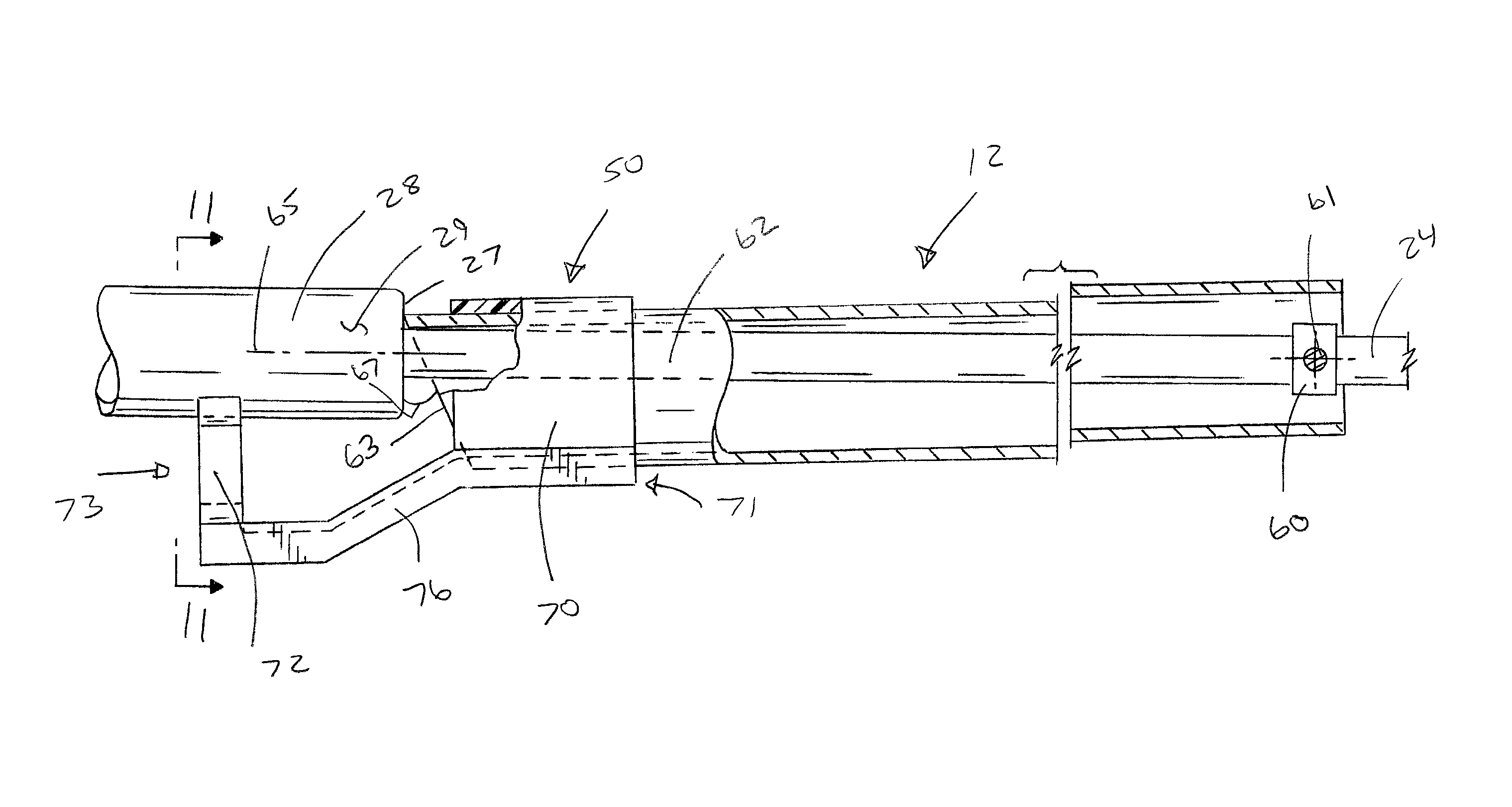
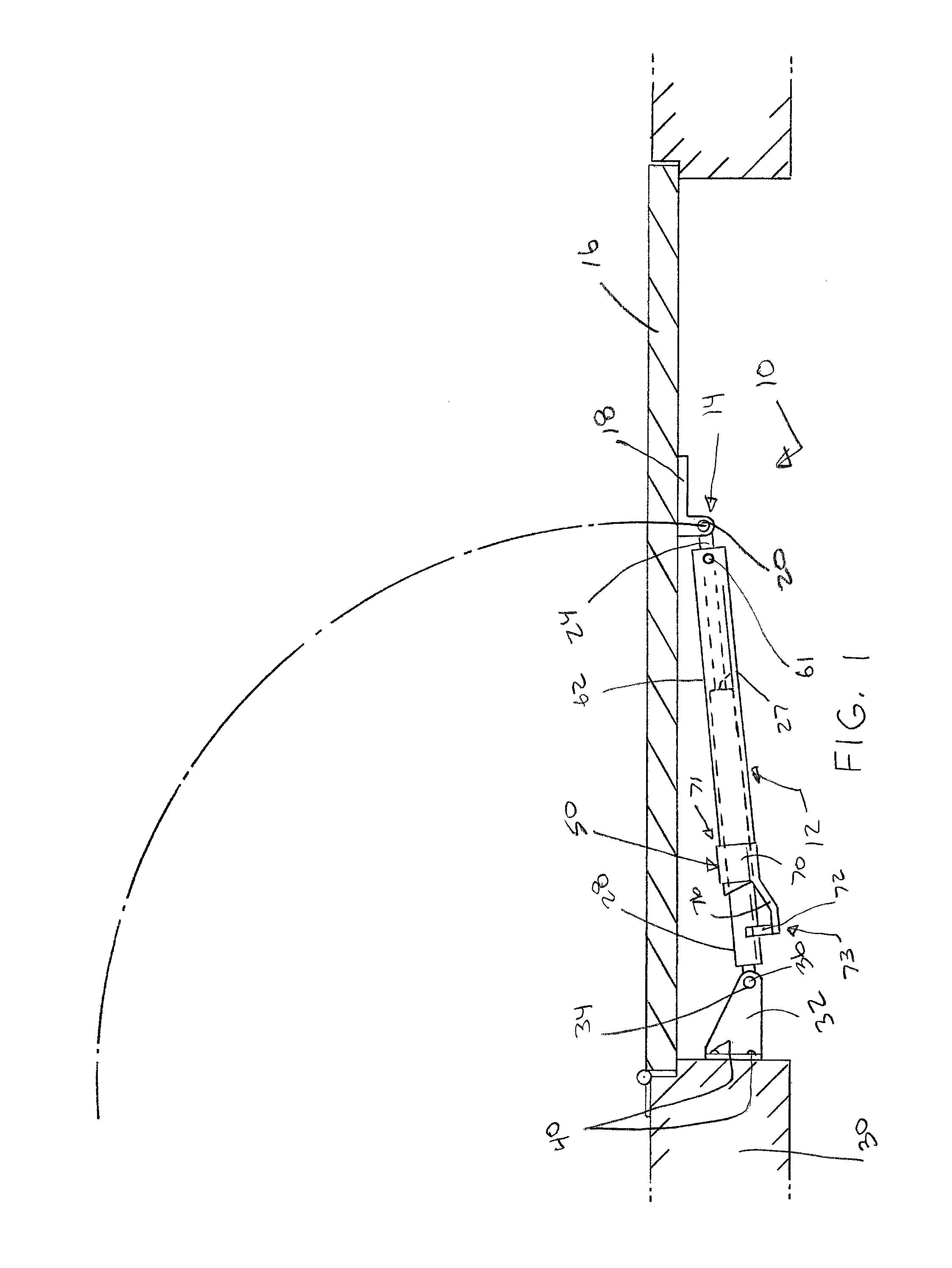
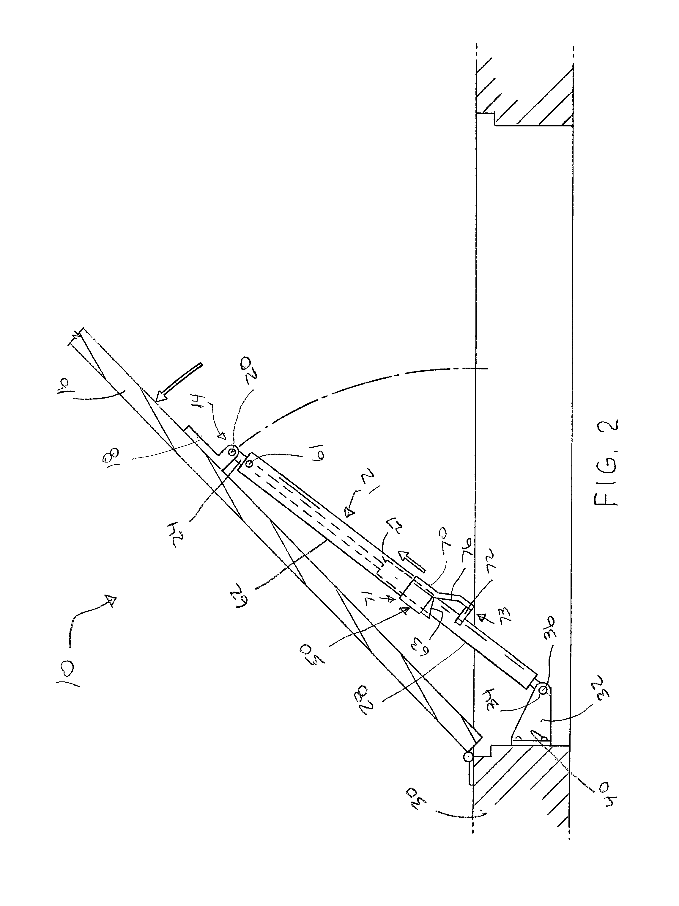
[0053]Making reference again to the drawings wherein like numerals indicate like or corresponding parts throughout the several figures, a new and improved door closer hold-open apparatus will be described. FIGS. 1-12 show a universal strut assembly according to the present disclosure. The universal strut assembly includes strut cylinder 28, strut rod 24, stop tube 50, locking tube 62, and pivot block 60. The strut assembly 10 is shown as being substantially about a central axis 65 (defined by centers of the strut cylinder 28 and strut rod 24) which can extend, for example, the length of the closer between the frame pivot 36 on the frame bracket 32 at a first end to an opposing bracket 18 and pin 20 at a second end.

[0054]It is to be appreciated that the stop tube 50 can be used for a multitude of different applications and mountings, and retrofitted to any strut size. The locking tube 62 can be anchored at one end to the strut rod 24. The pivot block 60 enables the locking tube 62 to...

second embodiment

[0061]To disengage the stop tube 150 and strut cylinder 128, the clip end 172 can be pushed towards the strut cylinder 128. The pressure expands the clip end 172 partially around the strut cylinder 128 thereby aligning the stop tube 150, strut cylinder 128, and locking tube 162 about the central axis (FIG. 13). The stop tube 150 holds the locking tube 162 in disengaged position until the strut cylinder 128 and locking tube 162 are partially closed. The stop tube 150 is “reset” when the strut assembly 110 is closed partially after the disengaging the terminal ends of the stop tube 150 and strut cylinder 128. The ramp 176, between the clip 172 and collar 170, resets the stop tube 150 when the strut assembly 110 is partially closed after disengagement. In the second embodiment, an angled portion or face 153 of the terminal end of the stop tube 150 provides for self-alignment between the strut cylinder 128 and the locking tube 162 about the central axis. It is to be appreciated that upo...


PUM


Abstract

A strut assembly is provided including a holding and releasing mechanism adapted to be attached to a cylinder-type closer. The mechanism comprises the strut assembly including a strut cylinder, a strut rod, a pivot block, and a locking tube. The strut assembly further comprises a stop tube including a clip at a first end and a collar at a second end. The stop tube further includes a rigid angled ramp connecting the clip and the collar. The clip moves from a first position to a second position while pivoting the locking tube at a first end in order to engage the locking tube at another end with the strut cylinder thereby holding the strut assembly in an extended position.

Description

FIELD OF THE INVENTION[0001]The invention relates in general to the difficulty of manipulating a self-closing strut under certain conditions. The present invention relates to universal stop tubes and strut assemblies; for example, door holders and door closers. The present disclosure provides improvements in holding open and facilitating closure of struts, door holders, and closers for use in all types of doors, latches, and lids, etc. The present disclosure provides a device for maintaining a strut assembly in a particular self-actuated, opened, and locked orientation and facilitating closure subsequent thereto.BACKGROUND OF THE INVENTION[0002]Door and latch closures, as well as strut closures, are known in the art. Strut assemblies or holders are utilized for holding side pivoted, i.e., hinged doors open against the self-closing action (or other closing action) of such a door closer. This closing action of the door closer or strut can be actuated by mechanical springs, nitrogen ga...

Claims


Application Information

Patent Timeline
Patent Type & Authority Patents(United States)
IPC IPC(8): E05F3/22E05F1/10F16F9/56
CPCE05F3/22E05F1/1091E05F1/10F16F9/56Y10T16/593Y10T16/61Y10T16/27Y10T16/281E05Y2201/218E05F3/221E05Y2900/136E05C17/30
Inventor ADOLINE, JACK
Owner BARNES GROUP
Why Eureka
Try Eureka