Equal phase and equal phased slope metamaterial transmission lines

a transmission line and equal phase technology, applied in the field of anti-ennas, can solve the problems of increasing phase slope, limited phase bandwidth, expanding physical footprint,

Active Publication Date: 2015-07-21
THE UNITED STATES OF AMERICA AS REPRESENTED BY THE SECRETARY OF THE NAVY
View PDF11 Cites 9 Cited by
  • Summary
  • Abstract
  • Description
  • Claims
  • Application Information

AI Technical Summary

Benefits of technology

The present invention relates to methods for designing a plurality of metamaterial transmission lines (MTM TLs) for a phased array antenna. The invention allows for the creation of a composite right / left hand (CRLH) TL architecture for a CRLH unit cell, which can be used to create a family of unit cells with different phases. By combining different numbers of CRLH unit cells with conventional right hand TLs, a plurality of transmission lines (TLs) can be created that have the same overall phase and an overall phase slope over the entire design frequency band for the antenna. The technical effects include improved performance and efficiency of phased array antennas.

Problems solved by technology

One challenge in phased array antenna design can be to minimize the respective physical footprint occupied by the supporting RF circuits (which includes the transmissions lines).
In addition, this length dependency on phase can result in increasing phase slopes, as the lines increase in physical length.
This creates a variety of different problems, including an expanding physical footprint.
Another problem can be a limitation in phase bandwidth that arises from TL's of different physical lengths having different phase slopes.
When conventional TL's of different lengths exhibit this phase slope behavior, this can lead to a variety of performance issues for the antenna.
The increasing different phase values (due to the drift in phase slope) can result in a radiation pattern for the array that can begin to diverge and scatter as a function frequency, since each antenna element in the array no longer maintains a uniform phase difference.
The prior art using conventional transmission lines and MTM TL's does not disclose constructing a family of MTM TL's that can achieve both equal phase and phase slope response.

Method used


Image

  • Equal phase and equal phased slope metamaterial transmission lines
  • Equal phase and equal phased slope metamaterial transmission lines
  • Equal phase and equal phased slope metamaterial transmission lines

Examples


Embodiment Construction

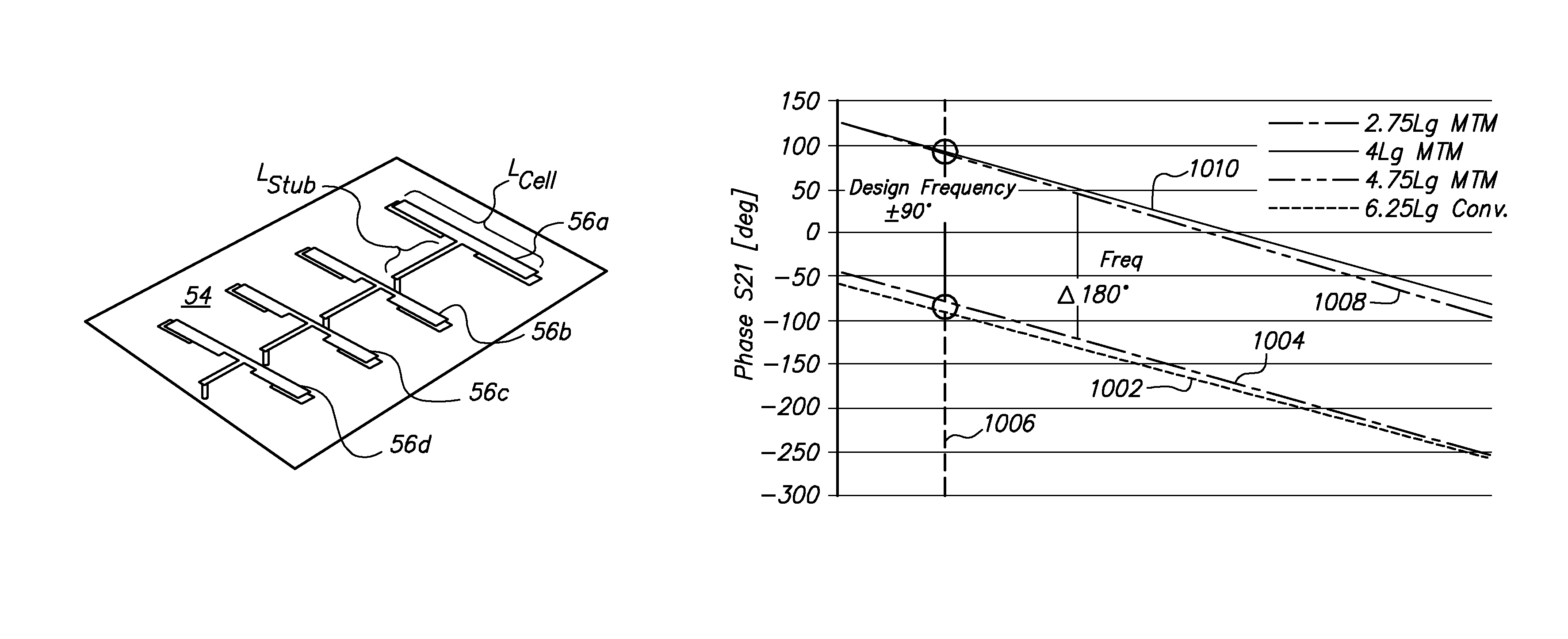
[0023]In brief overview of the prior art, one challenge in antenna phased array antenna design is to minimize the footprint occupied by the supporting RF circuits. Transmission lines in the feed networks of phased antenna arrays function to divide input power equally among the array elements, and they are used to appropriately phase each of the antenna elements in the array. The transmission lines (TL's) in the prior art must be designed to be a certain physical length in order to achieve a desired phase shift at a design frequency fo for the antenna (hereinafter, the term “antenna” shall refer to phased array antennas). This phase dependency on length can result in lines that must be “meandered” in order to maintain a small physical size footprint, as in the case of passive phased arrays.

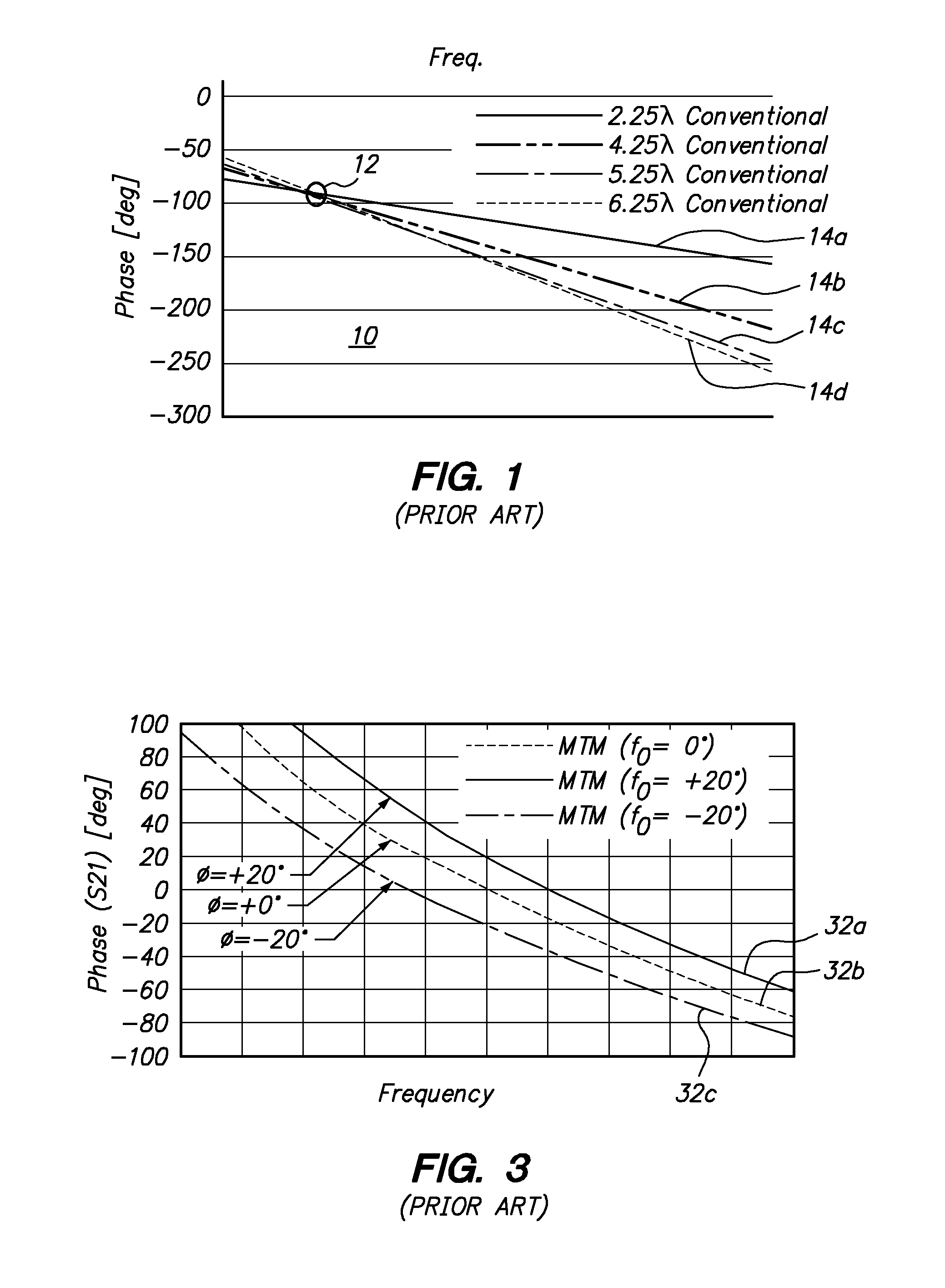
[0024]In addition, this length dependency on phase results in increasing phase slopes over the design frequency band of the antenna, as a function of frequency, as the lines increase in physical le...


PUM


Abstract

Methods for establishing metamaterial transmission line (MTM TL's) for a phased array antenna can include the initial step of defining a defining a Composite Right / Left Hand (CRLH) CRLH unit cell architecture. A family of unit cells using CRLH TL microstrip architecture can be constructed so that each of the CRLH unit cells have the same physical length, but different cell phases and cell phase slopes. To do this, the stub length of each CRLH unit cell can be varied. Once the family of CRLH unit cells is constructed, different numbers of different CRLH unit cells from the family can be combined with different numbers of conventional right hand TL's, which results in TL's for a phased array antenna that each have the same overall phase and overall phase slope not only at the design frequency f0, but over the entire design frequency band for the antenna.

Description

FEDERALLY-SPONSORED RESEARCH AND DEVELOPMENT[0001]This invention (Navy Case No. 101813) is assigned to the United States Government and is available for licensing for commercial purposes. Licensing and technical inquires may be directed to the Office of Research and Technical Applications, Space and Naval Warfare Systems Center, Pacific, Code 72120, San Diego, Calif. 92152; voice (619) 553-5118; email ssc pac T2@navy.mil.FIELD OF THE INVENTION[0002]The present invention pertains generally to antennas. More specifically, the present invention pertains to metamaterial transmission lines (MTM TL's) for phased array antennas. The invention is particularly, but not exclusively useful as a device and a method of designing a family of different length MTM TL's for phased array antennas, so that each MTM TL in the family achieves the desired phase at the design frequency, with equal phase slope over the entire design bandwidth.BACKGROUND OF THE INVENTION[0003]Phased array antennas are well ...

Claims


Application Information

Patent Timeline
IPC IPC(8): H01P3/08H01P1/18H01P11/00H01Q3/26
CPCH01P3/08H01P11/003H01Q3/26H01Q15/0086
Inventor CHURCH, JUSTIN A.MELOLING, JOHNROCKWAY, JOHN D.
Owner THE UNITED STATES OF AMERICA AS REPRESENTED BY THE SECRETARY OF THE NAVY
Why Eureka
Try Eureka