Filtering unit and relative filtering cartridge
a filtering unit and cartridge technology, applied in the direction of filtration separation, stationary filtering element filters, dispersed particle filtration, etc., can solve the problems of increasing the production cost of the filtering cartridge and the casing, not easy to decouple in an equally quick and easy manner, and bayonet-like couplings reveal some drawbacks
- Summary
- Abstract
- Description
- Claims
- Application Information
AI Technical Summary
Benefits of technology
Problems solved by technology
Method used
Image
Examples
first embodiment
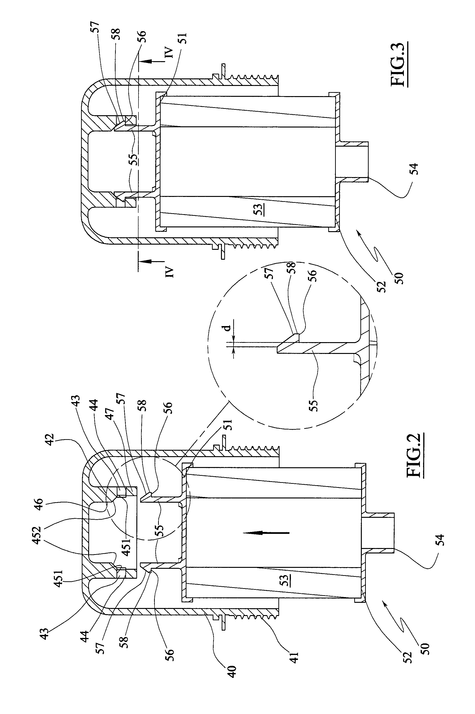
[0031]FIG. 2 is a longitudinal sectional view of a filtering cartridge in a first position before coupling to the support body obtained in the cover of the casing, according to the filtering unit, and the relative enlarged detail.
[0032]FIG. 3 is a view of FIG. 2 with the filtering cartridge in coupled position.
[0033]FIG. 4 is the view along the line of section IV-IV of FIG. 3.
[0034]FIG. 5 is a longitudinal sectional view of the filtering cartridge of FIG. 2 in a first decoupling position.
[0035]FIG. 6 is the view along the line of section VI-VI of FIG. 5.
[0036]FIG. 7 is a longitudinal sectional view of the filtering cartridge of FIG. 2 in a second decoupling position.
[0037]FIG. 8 is the view along the line of section VIII-VIII of FIG. 7.
[0038]FIG. 9 is a longitudinal sectional view of the filtering cartridge of FIG. 2 in a decoupled configuration.
second embodiment
[0039]FIG. 10 is a longitudinal sectional view of the filtering cartridge in a first position before coupling to the cover, according to the filtering unit, and the relative enlarged detail.
[0040]FIG. 11 is a view of FIG. 10 with the filtering cartridge in a coupled position.
[0041]FIG. 12 is the view along the line of section XII-XII of FIG. 11.
[0042]FIG. 13 is a longitudinal sectional view of the filtering cartridge of FIG. 10 in a first de coupling position.
[0043]FIG. 14 is the view along the line of section XIV-XIV of FIG. 13.
[0044]FIG. 15 is a longitudinal sectional view of the filtering cartridge of FIG. 10 in a second decoupling position.
[0045]FIG. 16 is the view along the line of section XVI-XVI of FIG. 15.
[0046]FIG. 17 is a longitudinal sectional view of the filtering cartridge of FIG. 10 in a decoupled configuration.
[0047]FIG. 18 is a view of a detail regarding the coupling element of FIG. 17.
PUM
| Property | Measurement | Unit |
|---|---|---|
| angle | aaaaa | aaaaa |
| angle | aaaaa | aaaaa |
| internal volume | aaaaa | aaaaa |
Abstract
Description
Claims
Application Information
 - R&D
- Intellectual Property
- Life Sciences
- Materials
- Tech Scout
- Unparalleled Data Quality
- Higher Quality Content
- 60% Fewer Hallucinations
Browse by: Latest US Patents, China's latest patents, Technical Efficacy Thesaurus, Application Domain, Technology Topic, Popular Technical Reports.
© 2025 PatSnap. All rights reserved.Legal|Privacy policy|Modern Slavery Act Transparency Statement|Sitemap|About US| Contact US: help@patsnap.com


