Filtering unit and relative filtering cartridge

a filtering unit and cartridge technology, applied in the direction of stationary filtering element filters, dispersed particle filtration, liquid separation agents, etc., can solve the problems of increasing the production cost of the filtering cartridge and the casing, not easy to decouple in an equally quick and easy manner, and the bayonet-like couplings reveal some drawbacks

Active Publication Date: 2014-06-05
UFI INNOVATION CENT
View PDF7 Cites 15 Cited by
  • Summary
  • Abstract
  • Description
  • Claims
  • Application Information

AI Technical Summary

Benefits of technology

[0028]Advantageously the distance between the coupling surface of the tooth and the top part ther...

Problems solved by technology

However, these bayonet-like couplings reveal some drawbacks mainly due to the required complexity of the coupling, especially for providing grooves in the cover.
Actually, such couplings of the bayonet-type are poorly reliable and scarcely resistant over time on one hand, especially after several replacements of the filtering cartridge and on the other hand they lead to an increase of the production costs of the filtering cartridge and the casing, as well as the costs due to the increase of the times required, in the maintenance interventions, for replacing the filtering cartridge, when for example upon the rotation imparted for opening the casing there corresponds an inadvertent decoupling of the bayonet coupling sy...

Method used


Image

  • Filtering unit and relative filtering cartridge
  • Filtering unit and relative filtering cartridge
  • Filtering unit and relative filtering cartridge

Examples


first embodiment

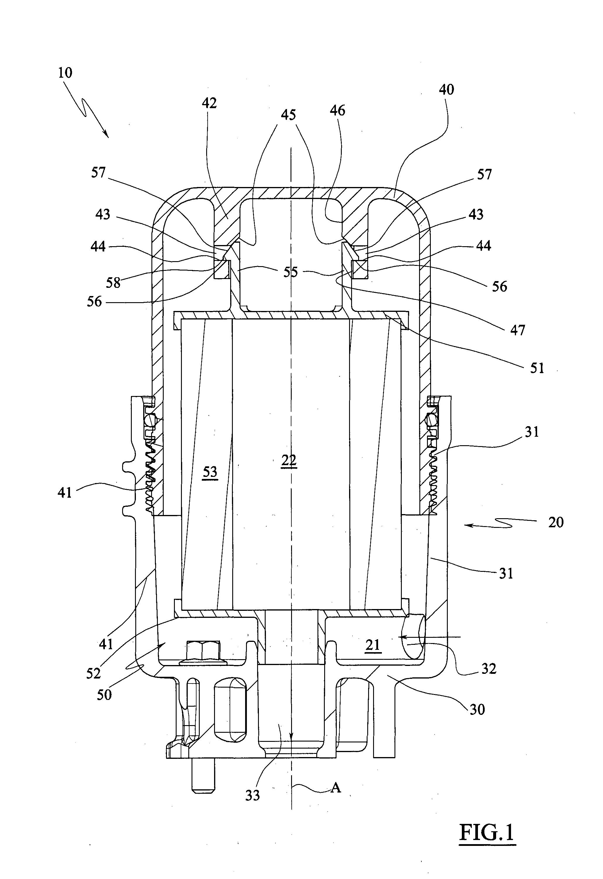
[0031]FIG. 2 is a longitudinal sectional view of a filtering cartridge in a first position before coupling to the support body obtained in the cover of the casing, according to the filtering unit, and the relative enlarged detail.

[0032]FIG. 3 is a view of FIG. 2 with the filtering cartridge in coupled position.

[0033]FIG. 4 is the view along the line of section IV-IV of FIG. 3.

[0034]FIG. 5 is a longitudinal sectional view of the filtering cartridge of FIG. 2 in a first decoupling position.

[0035]FIG. 6 is the view along the line of section VI-VI of FIG. 5.

[0036]FIG. 7 is a longitudinal sectional view of the filtering cartridge of FIG. 2 in a second decoupling position.

[0037]FIG. 8 is the view along the line of section VIII-VIII of FIG. 7.

[0038]FIG. 9 is a longitudinal sectional view of the filtering cartridge of FIG. 2 in a decoupled configuration.

second embodiment

[0039]FIG. 10 is a longitudinal sectional view of the filtering cartridge in a first position before coupling to the cover, according to the filtering unit, and the relative enlarged detail.

[0040]FIG. 11 is a view of FIG. 10 with the filtering cartridge in a coupled position.

[0041]FIG. 12 is the view along the line of section XII-XII of FIG. 11.

[0042]FIG. 13 is a longitudinal sectional view of the filtering cartridge of FIG. 10 in a first de coupling position.

[0043]FIG. 14 is the view along the line of section XIV-XIV of FIG. 13.

[0044]FIG. 15 is a longitudinal sectional view of the filtering cartridge of FIG. 10 in a second decoupling position.

[0045]FIG. 16 is the view along the line of section XVI-XVI of FIG. 15.

[0046]FIG. 17 is a longitudinal sectional view of the filtering cartridge of FIG. 10 in a decoupled configuration.

[0047]FIG. 18 is a view of a detail regarding the coupling element of FIG. 17.


PUM

PropertyMeasurementUnit
Angleaaaaaaaaaa
Angleaaaaaaaaaa
Angleaaaaaaaaaa

Abstract

A filtering unit (10) comprising a casing (20) provided with at least one inlet (32), one outlet (33) and one support body (42) provided with abutment surfaces (44) adapted to removably support a filtering cartridge (50) contained within the casing (20) and adapted to divide the internal volume of the casing (20) into two chambers (21,22) respectively connected with the inlet (32) and the outlet (33) so as to filter the fluid flowing from the inlet (32) towards the outlet (33), the filtering cartridge (50) comprising at least one coupling element (55) configured to be snap-coupled to the support body (42) following a first axial translation for mutual approaching between the filtering cartridge (50) and the support body (42), whose distinctive characteristic lies in the fact that it comprises cam means (57,58) operating between the coupling element (55) and the support body (42) so as to radially bend the coupling element (55) in a release position for disengaging the coupling element (55) from the support element (42) following a further limited mutual axial translation between the filtering cartridge (50) and the support body (42), moving in the same direction with respect to the first approaching translation, the cam means (57,58) being configured so as to keep the coupling element (55) in release position following a slight mutual rotation between the filtering cartridge (50) and the support body (42).

Description

FIELD OF THE INVENTION[0001]The present invention regards a filtering unit and the relative filtering cartridge.[0002]Mainly the invention regards a unit for filtering lubricant oil, air or fuel in automotive applications, more in particular in applications in which there is required a high flow rate of such fluids from the filter, such as for example trucks, buses, commercial vehicles and work machines or where there is required a medium fluid flow rate, like in the motor vehicle industry.PRIOR ART[0003]As known the filtering of lubricant fluids in the automotive industry is generally obtained by means of a filtering unit comprising an external casing provided with an inlet for the fluid to be filtered and an outlet for the filtered fluid, and a filtering cartridge adapted to define a chamber, internal or external, communicating with the inlet of the fluid to be filtered.[0004]Thus, the fluid flowing from the inlet towards the outlet of the filter is forced to traverse the filterin...

Claims


Application Information

Patent Timeline
IPC IPC(8): B01D29/13B01D46/24
CPCB01D46/2414B01D2201/291B01D2201/4007B01D2201/4084B01D2265/028B01D2201/305B01D29/13B01D46/0002B01D46/0005B01D46/2411
Inventor GIRONDI, GIORGIO
Owner UFI INNOVATION CENT
Why Eureka
Try Eureka