Position sensor

a technology of resonant frequency and stylus, which is applied in the direction of instruments, cathode-ray tube indicators, power supplies for data processing, etc., can solve the problems of insufficient single measurement of the resonant frequency of the stylus to determine whether it is clicked or unclicked, requires user cooperation, and difficult prediction, etc., to achieve the effect of small nib-click distan

Inactive Publication Date: 2009-07-23
SINNAPTIX
View PDF100 Cites 48 Cited by
  • Summary
  • Abstract
  • Description
  • Claims
  • Application Information

AI Technical Summary

Benefits of technology

[0013]According to one aspect, the present invention provides a system which does not require a special tuning step. The stylus is designed so that its unclicked resonant frequency will always lie within a predefined “unclicked frequency band” and so that its clicked resonant frequency will always lie within a “clicked frequency band”. The processing electronics then measures the frequency of the stylus and reports clicked if that measurement exceeds the decision frequency and unclicked if it is lower than the decision frequency. In the preferred embodiment, this is achieved while maintaining a relatively small nib-click distance (i.e., the distance the nib has to move between the clicked and unclicked states) so that the writing action of the stylus is similar to that of a conventional pen.

Problems solved by technology

As a result, a single measurement of the resonant frequency of the stylus may be insufficient to determine whether it is clicked or unclicked.
However, such a tuning technique has the drawback that it requires cooperation from the user.
However, such prediction is difficult and for low-powered devices (such as hand-held battery-powered devices) requires excessive power to be drawn from the battery if the stylus is to be tracked continuously.
Further, without continuous tracking, it is difficult to detect the condition where a user swaps between two styluses with different frequencies (which might occur if several styluses are provided, each associated with a different function, such as writing and erasing).
Another problem associated with the stylus design described in WO 00 / 33244 is that the resonant frequency of the stylus can reduce significantly if the stylus is rested flat on the writing surface, due to magnetic screening used behind the sensor board of the hand-held device.
In this case, the processor may erroneously report that the stylus has been clicked.
However, with the design of stylus described in WO 00 / 33244, this would require significant movement of the nib of the stylus between the clicked and unclicked states, which would feel unacceptably large for users.

Method used


Image

  • Position sensor
  • Position sensor
  • Position sensor

Examples


Embodiment Construction

Overview of Digitizing System

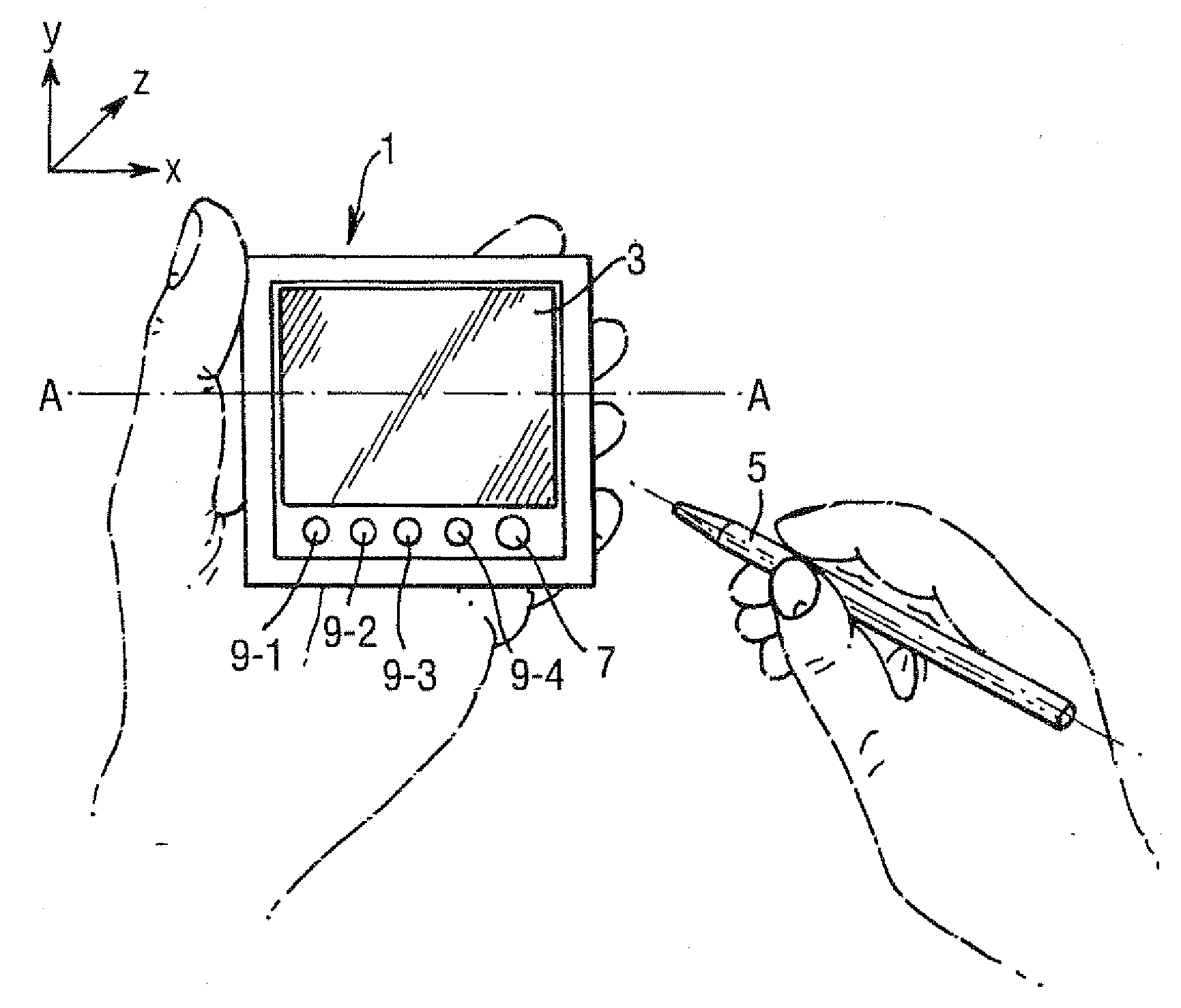
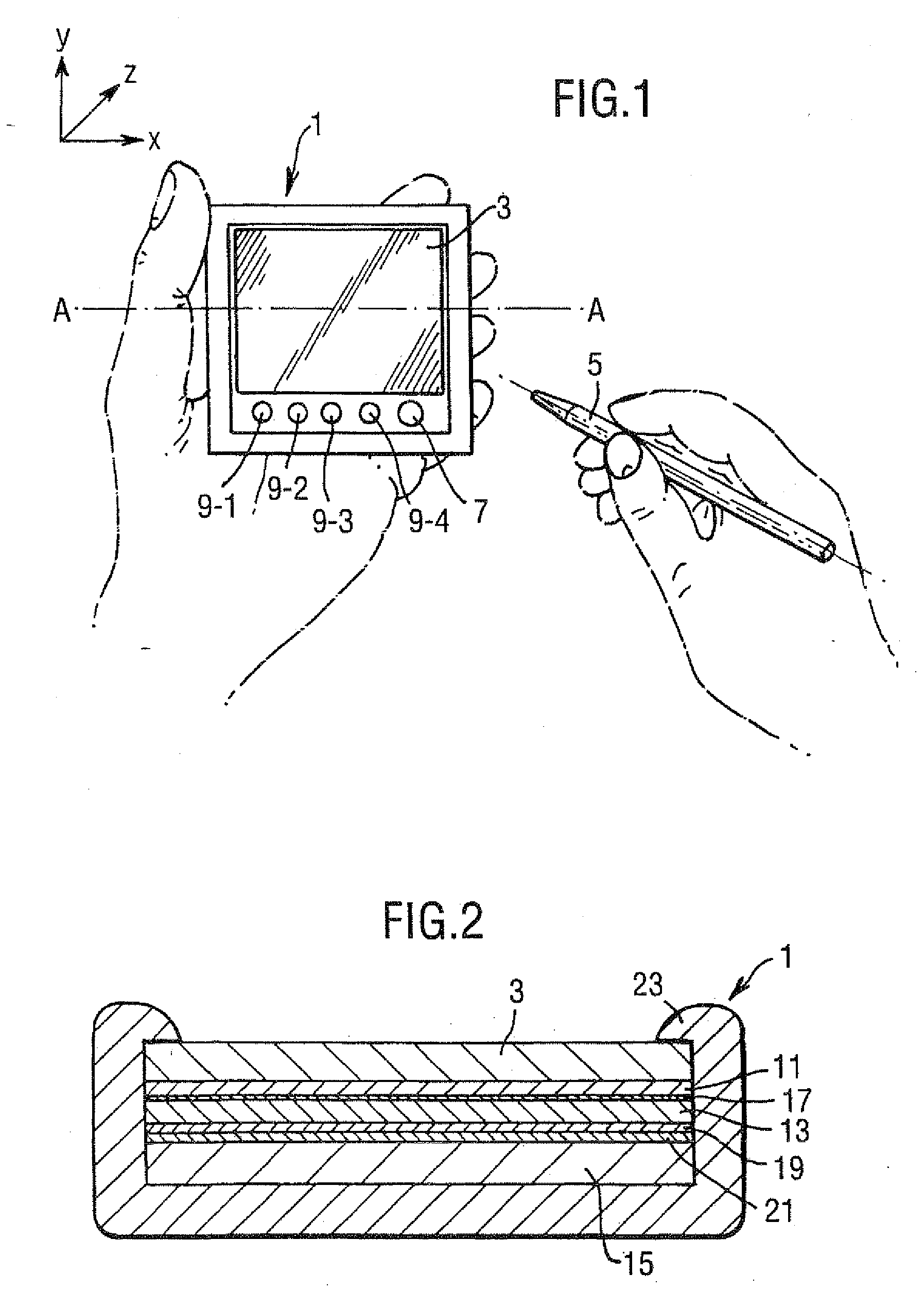
[0050]FIG. 1 shows a hand-held battery-powered personal digital assistant (PDA) 1 which employs an x-y digitizing system (not shown) which is located beneath a liquid crystal display 3 of the PDA 1. The x-y digitizing system is operable to detect the presence and x-y position of a resonant stylus 5 relative to the LCD 3. The position signals output from the digitizing system are used by the PDA 1 to control information that is displayed on the LCD 3 and to control the operating function of the PDA 1. As shown, the PDA 1 also includes a number of push buttons beneath the LCD 3, including an on-off button 7 and a number of control buttons 9-1 to 9-4 which are used to control different functions of the PDA 1.

[0051]FIG. 2 shows a cross-sectional view on A-A of the PDA 1 shown in FIG. 1. As shown, the PDA 1 includes a liquid crystal display 3 which, in this embodiment, is between 1.5 mm and 3 mm thick. Beneath the LCD 3, there is an electroluminescent backlig...


PUM


Abstract

A low-cost x-y digitizing system for use in consumer electronic devices, such as portable digital assistants, mobile telephones, web browsers and the like. The digitizer includes a resonant stylus, an excitation winding for energizing the resonant stylus and a set of sensor windings for sensing the signal generated by the stylus, from which the x-y position of the stylus is determined. A novel stylus design is described together with novel digitizer windings and novel excitation and processing circuitry.

Description

RELATED APPLICATIONS[0001]This is a division of U.S. Ser. No. 10 / 478,354 filed May 6, 2004 (now U.S. Pat. No. ______ issued ______, 2009), which was a U.S. national phase of International Application No. PCT / GB02 / 02387 filed May 21, 2002, which designated the U.S., the entire contents of all of which are hereby incorporated by reference.BACKGROUND[0002]1. Technical Field[0003]The present invention relates to a position sensor and to parts therefor. The invention has particular, although not exclusive, relevance to stylus input computer and communication devices, particularly small, low-cost devices, such as personal digital assistants (PDAS), mobile telephones, web browsers and combinations of these. The invention has particular relevance where those computer and communication devices are battery-powered.[0004]2. Related Art[0005]Several pen or stylus sensing systems for computer input exist. For example, U.S. Pat. No. 4,878,553 and the applicants' earlier International Application ...

Claims


Application Information

Patent Timeline
Patent Type & Authority Applications(United States)
IPC IPC(8): G06F3/041G06F1/32G06F3/0354G06F3/046
CPCG06F1/3203G06F1/3262G06F2203/0339G06F3/03547G06F3/046G06F3/03545
Inventor SILK, CHRISTOPHER J.ELY, DAVID T.E.ERRINGTON, ANDREW M.COLLINS, IANFOOTE, GEOFFREYHAINES, JULIANBOLENDER, ROBERTMCCAUGHAN, GARETH J.
Owner SINNAPTIX
Why Eureka
Try Eureka