Microfluidics System for Sequencing

a microfluidics and sequencing technology, applied in the field of sensing, can solve the problems of high cost and the inability to wash the sample, and achieve the effects of small distance to be travelled in the microfluidics network, high throughput, and limited washing time and reagentia

Active Publication Date: 2013-11-07
INTERUNIVERSITAIR MICRO ELECTRONICS CENT (IMEC VZW)
View PDF2 Cites 51 Cited by
  • Summary
  • Abstract
  • Description
  • Claims
  • Application Information

AI Technical Summary

Benefits of technology

[0009]It is an advantage of embodiments of the present invention that a microfluidic biosensor with a high throughput can be obtained. It is an advantage of embodiments of the present invention that the washing time and reagentia used for washing can be limited.
[0010]It is an advantage of embodiments of the present invention that the flow in at least different sets of microfluidic channels, and more advantageously in some embodiments in each of the microfluidic channels can be controlled independent from other micro-fluidic channels. It is an advantage of at least some embodiments that the flow in the micro-fluidic channels can be based on a negative pressure that is applied, e.g. in common, to the plurality of micro-fluidic channels, externally to the micro-fluidic chip.
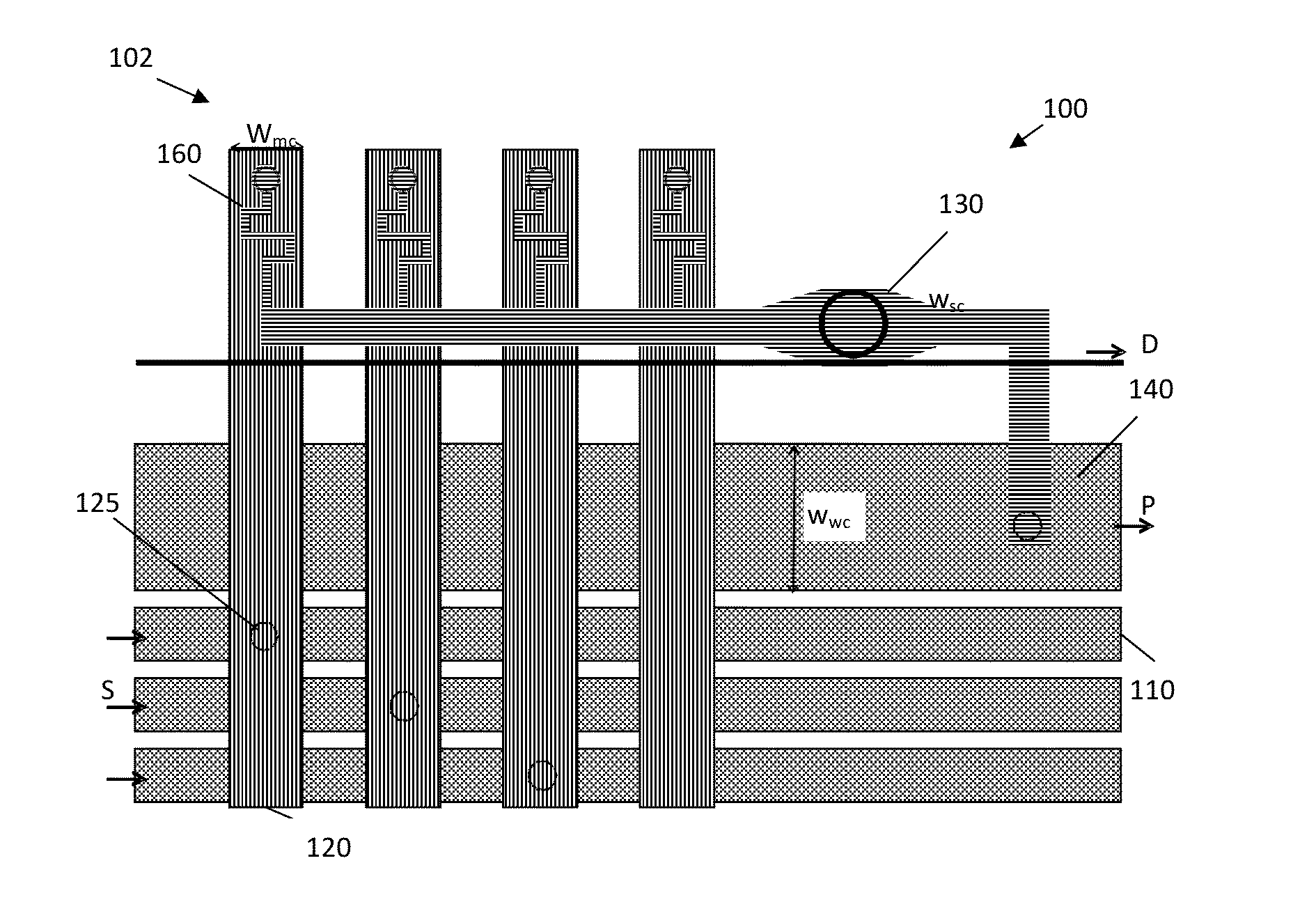
[0011]It is an advantage of embodiments of the present invention that the distance to be travelled in the microfluidics network is small so that the amount of product required for operating the device can be small. The amount of product wasted therefore is reduced. It is an advantage of embodiments of the present invention that the amount of reagentia required, e.g. for washing, can be limited: a general washing step for the complete chip is avoided, instead washing is performed per channel thereby reducing the amount of fluid.
[0012]It is an advantage of embodiments of the present invention that the microfluidic biosensing device can make us of densely positioned sensors, allowing a high throughput.

Problems solved by technology

A washing step contributes to higher costs as large amounts of reagents are needed in the case of sequencing by synthesis.

Method used


Image

  • Microfluidics System for Sequencing
  • Microfluidics System for Sequencing
  • Microfluidics System for Sequencing

Examples


Embodiment Construction

[0038]The present invention will be described with respect to particular embodiments and with reference to certain drawings but the invention is not limited thereto but only by the claims. The drawings described are only schematic and are non-limiting. In the drawings, the size of some of the elements may be exaggerated and not drawn on scale for illustrative purposes. The dimensions and the relative dimensions do not correspond to actual reductions to practice of the invention.

[0039]Furthermore, the terms first, second and the like in the description and in the claims, are used for distinguishing between similar elements and not necessarily for describing a sequence, either temporally, spatially, in ranking or in any other manner. It is to be understood that the terms so used are interchangeable under appropriate circumstances and that the embodiments of the invention described herein are capable of operation in other sequences than described or illustrated herein.

[0040]Moreover, t...


PUM

PropertyMeasurementUnit
sizeaaaaaaaaaa
sizeaaaaaaaaaa
cycle timeaaaaaaaaaa

Abstract

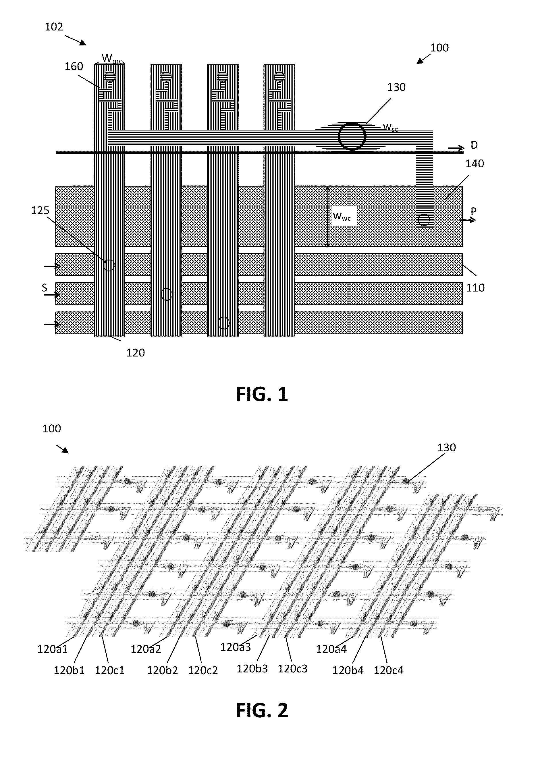
A microfluidic chip (100) for use in multiplexed analysis of samples is described. The microfluidic chip (100) comprises a plurality of sensing chambers (130) and further comprises at least a first fluid supply channel (110) for providing a first fluid and a plurality of microfluidic channels (120). These are in fluid communication with at least one sensing chamber (130) and with the first fluid supply channel (110) for delivery of said first fluid to the at least one sensing chamber. The microfluidic channels (120) are branching off from the supply channel (110) in the neighbourhood of the sensing chamber (130) that can be provided with the first fluid through the microfluidic channel (120). The different channels (110, 120) thus form a tree-like delivery distribution system for supplying the first fluid to said plurality of sensing chambers (130).

Description

CROSS-REFERENCE TO RELATED APPLICATIONS[0001]This application claims the benefit of priority of European Patent Application no. 12166483.3, filed May 2, 2012, which is hereby incorporated herein by reference in its entirety.BACKGROUND OF THE INVENTION[0002]1. Field of the Invention[0003]The invention relates to the field of sensing such as for example biosensing. More particularly, the present invention relates to methods and systems for multiplexed, i.e. simultaneous, sensing or characterizing samples in microfluidic devices, such as for example used in sequencing applications.[0004]2. Technical Background[0005]For a number of sensing applications, such as for example different biosensing applications, the need for multiplexed processing is high. In several applications, a large number of sensing events needs to be performed for obtaining an accurate characterization of a sample. One example of such an application whereby a large number of sensing events are required is sequencing....

Claims


Application Information

Patent Timeline
Patent Type & Authority Applications(United States)
IPC IPC(8): C12Q1/68
CPCC12Q1/6869B01L3/5027B01L3/502707B01L2300/0816B01L2300/0864B01L2300/0874B01L2300/0887B01L2400/0487C12Q2565/629
Inventor PEUMANS, PETER
Owner INTERUNIVERSITAIR MICRO ELECTRONICS CENT (IMEC VZW)
Why Eureka
Try Eureka