Helmet with a chin strap buckle system

a technology of chin strap and buckle system, which is applied in the field of safety devices, can solve the problems of head injury risk for the user, player's head injury, and element to bear

Inactive Publication Date: 2015-09-08
WEGENER JAMES D
View PDF25 Cites 4 Cited by
  • Summary
  • Abstract
  • Description
  • Claims
  • Application Information

AI Technical Summary

Benefits of technology

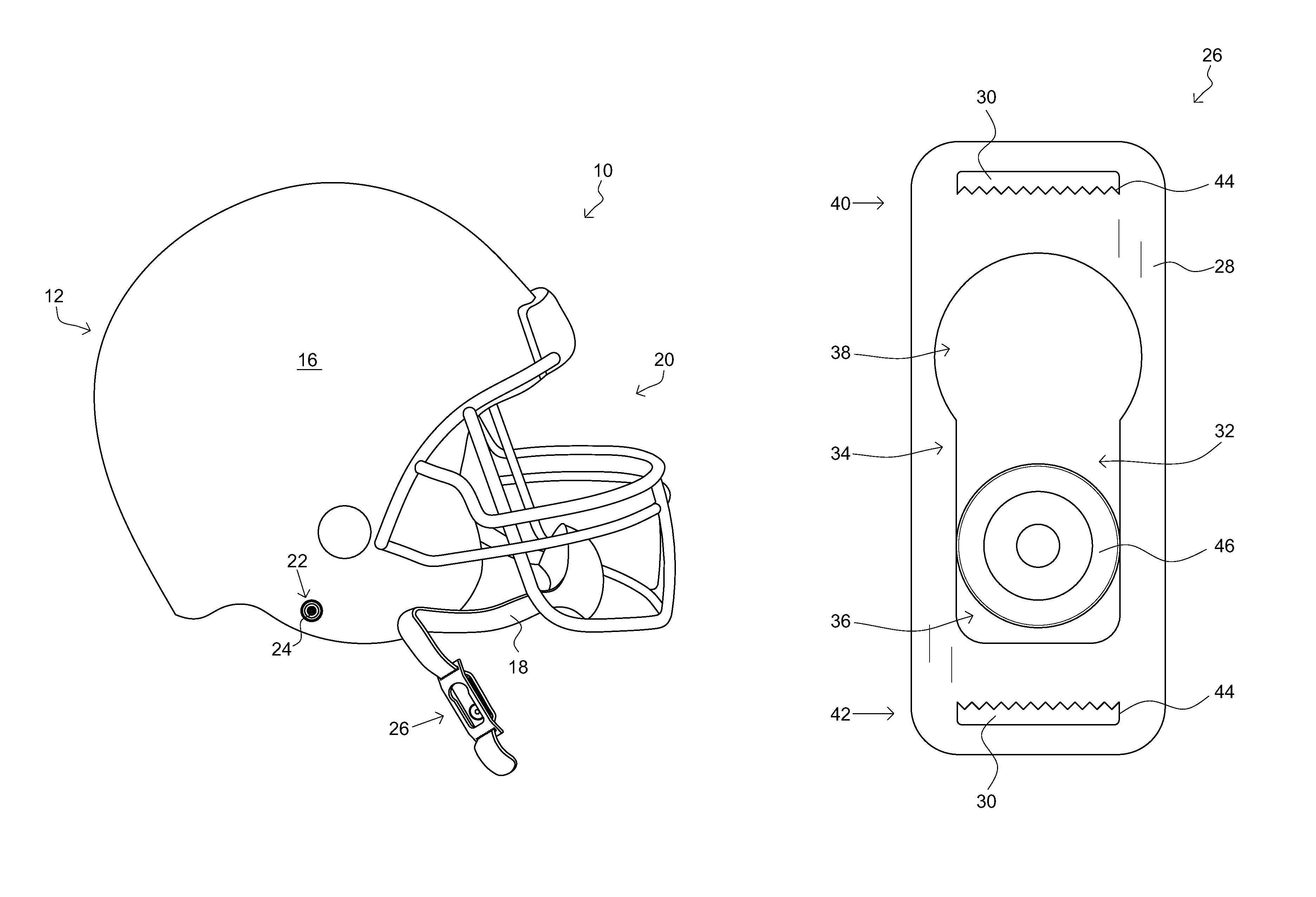
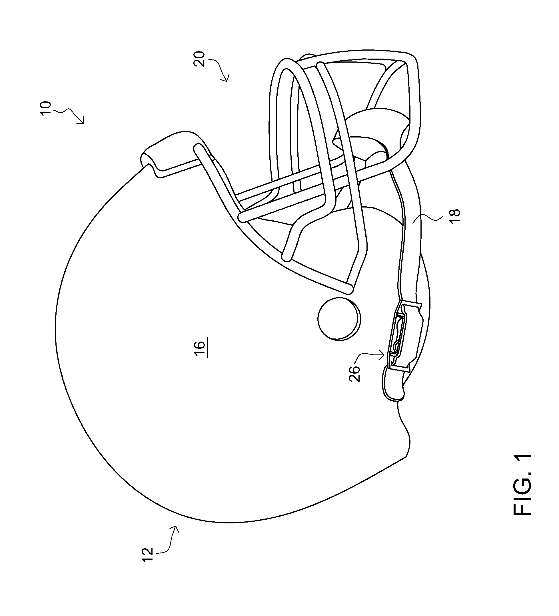
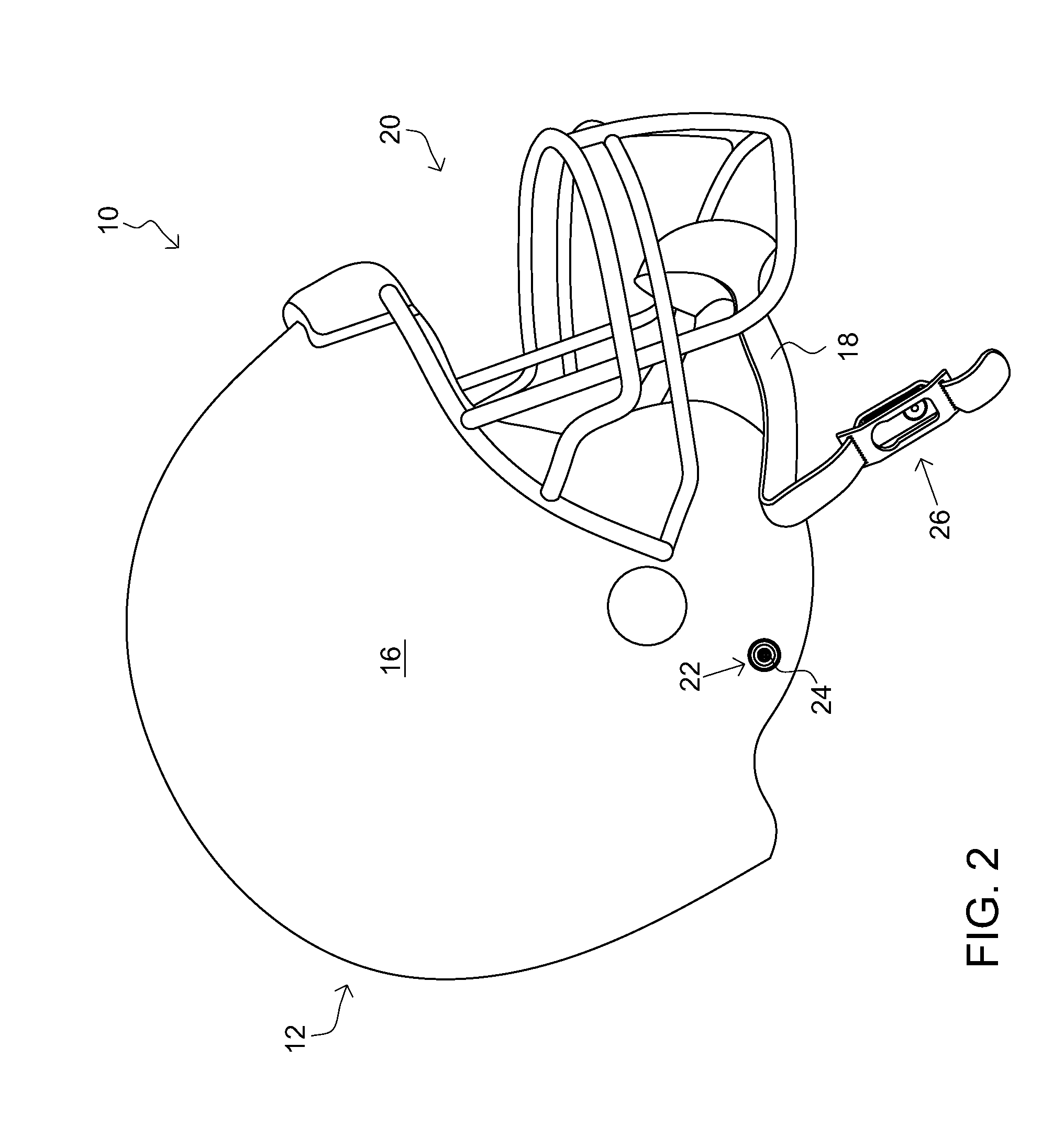
[0016]The helmet may include a buckle that may be coupled to the chin strap, and may be selectably coupleable to the anchor. The buckle may include a housing that may have a pair of strap slits. The pair of slits may each include a set of gripping teeth that may be disposed on a side of the slit. The set of gripping teeth of the pair of slits may be oriented so as to be facing oppositely from each other. The housing may includes a first end and a second end each may be extending from the housing at an angle and may be configured to assist in coupling and removing of the buckle from the anchor. The pair of slits may be disposed about the first end and the second end.

Problems solved by technology

Beside their energy-absorption capability, their volume and weight are also important issues, since higher volume and weight increase the injury risk for the user's head and neck.
Although they are protective, players can and do still suffer head injuries such as a concussion.
Thus, shortening or distending the connection portions reduces the distance between the helmet and the respirator mask and thereby causes the pressure element to bear against the frontpiece of the respirator mask, compressing the user's head between the helmet and the mask and thereby holding the mask against the user's face.
The inventions heretofore known suffer from a number of disadvantages which include being unsafe, being unable to securely couple a helmet to a wearer, being difficult to use, being uncomfortable, being unable to securely couple a chin strap to a helmet; being easily removed; being easily knocked off; coming unsnapped on impact; coming uncoupled when pressure is applied on the strap in a forward direction; being difficult to detach; and the like.

Method used


Image

  • Helmet with a chin strap buckle system
  • Helmet with a chin strap buckle system
  • Helmet with a chin strap buckle system

Examples


Embodiment Construction

[0030]For the purposes of promoting an understanding of the principles of the invention, reference will now be made to the exemplary embodiments illustrated in the drawing(s), and specific language will be used to describe the same. It will nevertheless be understood that no limitation of the scope of the invention is thereby intended. Any alterations and further modifications of the inventive features illustrated herein, and any additional applications of the principles of the invention as illustrated herein, which would occur to one skilled in the relevant art and having possession of this disclosure, are to be considered within the scope of the invention.

[0031]Reference throughout this specification to an “embodiment,” an “example” or similar language means that a particular feature, structure, characteristic, or combinations thereof described in connection with the embodiment is included in at least one embodiment of the present invention. Thus, appearances of the phrases an “em...


PUM


Abstract

A helmet including a protective head covering and a chin strap. The helmet includes an anchor protruding from the protective head covering and including an enlarged anchor head. The helmet includes a buckle coupled to the chin strap, and selectably coupleable to the anchor. The buckle includes a housing including a pair of strap slits. The buckle includes a cavity disposed in the housing and sized to contain the enlarged anchor head. The buckle includes a retaining slot having a retaining region sized to securely couple to the enlarged anchor head. The helmet includes a securement member disposed about the retaining slot. The helmet includes a second anchor and a second buckle; wherein the second anchor and the second buckle minor the anchor and the buckle disposed on the second side region of the protective head covering.

Description

BACKGROUND OF THE INVENTION[0001]1. Field of the Invention[0002]The present invention relates to safety devices, specifically to a helmet having a safety buckle system.[0003]2. Description of the Related Art[0004]A helmet is a form of protective gear worn on the head to protect it from injuries. All helmets attempt to protect the user's head by absorbing mechanical energy and protecting against penetration. Their structure and protective capacity are altered in high-energy impacts. Beside their energy-absorption capability, their volume and weight are also important issues, since higher volume and weight increase the injury risk for the user's head and neck. Anatomical helmets adapted to the inner head structure were invented by neurosurgeons at the end of the 20th century.[0005]Helmets used for different purposes have different designs. For example, a bicycle helmet must protect against blunt impact forces from the wearer's head striking the road. A helmet designed for rock climbin...

Claims


Application Information

Patent Timeline
Patent Type & Authority Patents(United States)
IPC IPC(8): A42B3/08A44B3/08A44B11/20
CPCA42B3/08A44B3/08A44B11/20
Inventor WEGENER, JAMES D.
Owner WEGENER JAMES D
Why Eureka
Try Eureka