Computer security lock for trapezoidal security slot

a computer and security lock technology, applied in the direction of instruments, locks for portable objects, internal/peripheral component protection, etc., can solve the problems of insufficient sturdiness and prone to breakage in some respects, interference with other internal components, and complexity

Active Publication Date: 2015-09-15
AVGANIM MEIR
View PDF37 Cites 9 Cited by
  • Summary
  • Abstract
  • Description
  • Claims
  • Application Information

AI Technical Summary

Problems solved by technology

The prior art rectangular security slot measuring 3×7 mm and having a rotatable T-bar locking element, e.g., 20, poses issues of complexity, insufficient sturdiness and proneness to breakage in some respects.
Another drawback of the prior art mechanism is that the T-bar locking element 20 needs to rotate behind the wall 24 of the piece of equipment and, as a result, can cause interference with other internal components.

Method used


Image

  • Computer security lock for trapezoidal security slot
  • Computer security lock for trapezoidal security slot
  • Computer security lock for trapezoidal security slot

Examples


Embodiment Construction

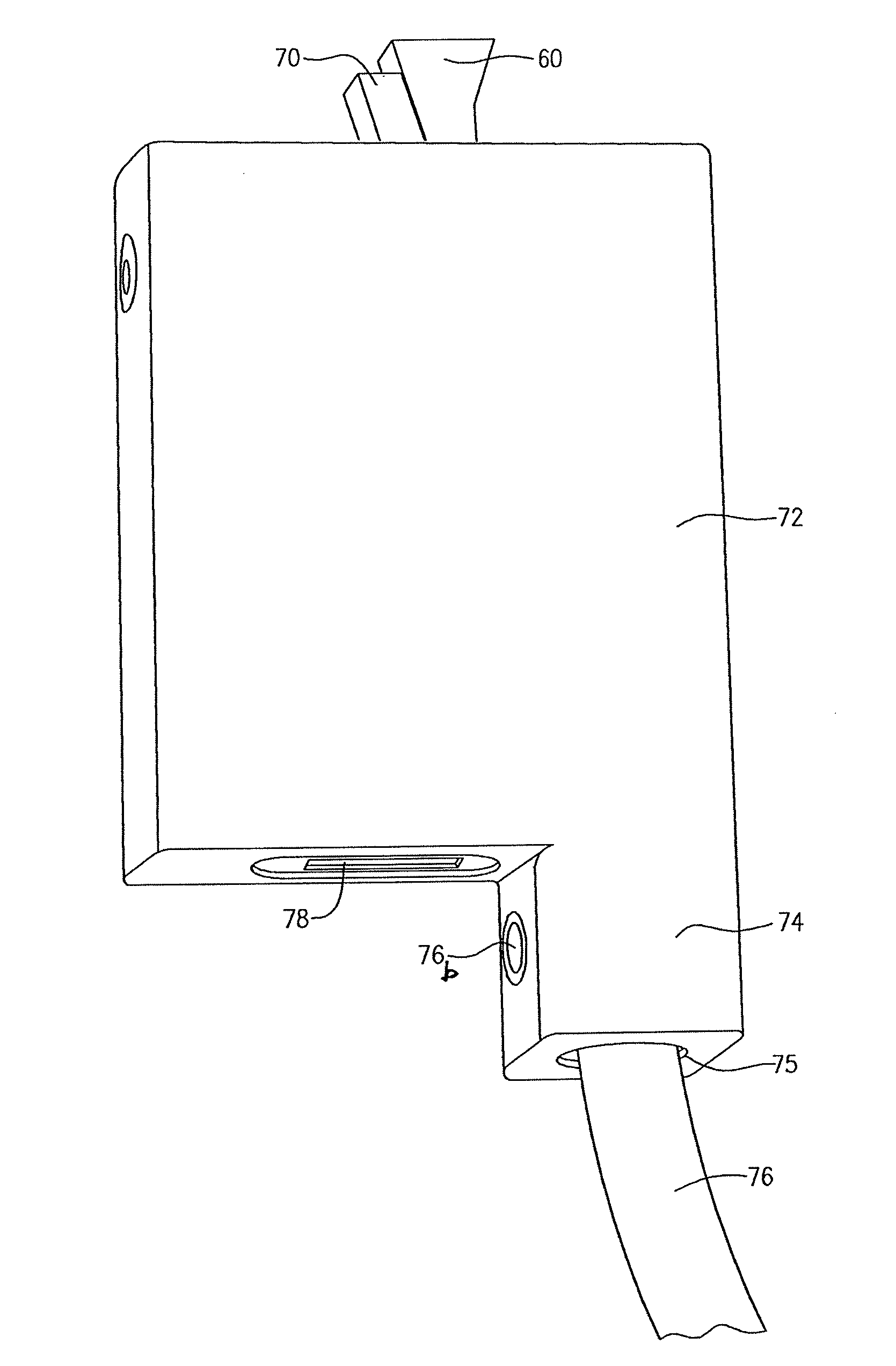
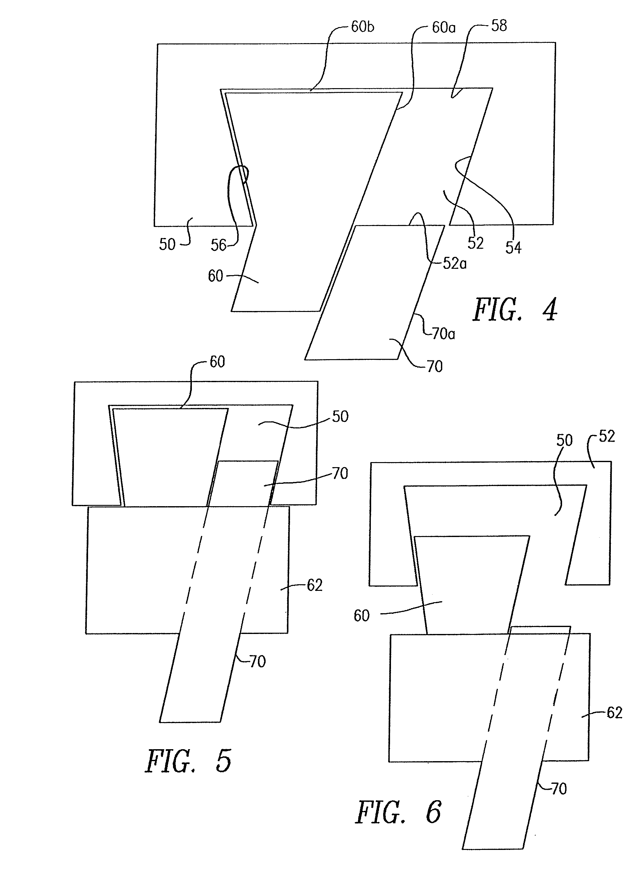
[0036]With reference to FIGS. 4-6, the locking principle of the present invention is described as follows. The body or wall 50 of equipment that needs to be secured against theft has formed therein a blind (or even through-going) cavity 52 with a generally rectangularly shaped opening 52a (FIG. 10a) which has outwardly tapering side walls 54 and 56 and a back wall 58, defining a trapezoidal shaped slot in a vertical cross section.

[0037]The complementary shaped locking element 60 has a leading lock body 60a which has a leading width 60b approximately equal, but slightly smaller than the width of the opening 52a. Therefore, the locking element 60 can be easily inserted into the cavity 52 and pushed to the left, enabling the slidable locking pin 70 to be pushed into the cavity 52, filling it and allowing the right side wall 70a thereof to engage the side wall 54 of the cavity 52. In this state, it is now impossible to pull on the locking element 60 and retrieve it from the cavity 52. T...


PUM


Abstract

A lock that is configured to be attached to electronic equipment requiring securing against theft and the lock comprising: a lock body; a locking element protruding from the lock body and having a forward distal section that is comparatively wider in cross-sectional size compared to a rear section thereof, the forward section being configured to be insertable into a cavity formed in the equipment, where the cavity is defined by an opening having a size and shape slightly larger than the cross-sectional size of the forward section of the locking element and an interior larger in cross-sectional size than the opening of the cavity; a slidable locking pin configured to slide alongside the locking element and into the cavity, after the locking element has been inserted into said cavity, to substantially fill a space of the cavity left unoccupied by the locking element; a sliding mechanism coupled to the locking pin and configured to slide the locking pin into and out of the cavity; and a locking mechanism to lock the locking mechanism within the lock body to prevent withdrawal of the locking element from the cavity.

Description

CROSS-REFERENCE TO RELATED APPLICATION[0001]This application claims benefit of and priority to U.S. Provisional Application Ser. No. 61 / 692,465 filed Aug. 23, 2012, as well as U.S. Provisional Application Ser. No. 61 / 585,849 filed Jan. 12, 2012, the contents of which are incorporated herein by reference.BACKGROUND OF THE INVENTION[0002]The present invention relates to devices for inhibiting the theft of relatively small but expensive pieces of equipment such as computers, telephones and the like. More specifically, the present invention is directed to a theft preventing lock for computers, tablets and the like, which has a locking element which is designed to be received in a trapezoidal or conical, security cavity or slot.[0003]The present invention is directed to a computer security lock of the type disclosed in U.S. Pat. No. 5,502,989, the contents of which are incorporated fully by reference herein. Prior art FIGS. 1, 2 and 3 herein correspond, respectively, to FIGS. 2, 9 and 13...

Claims


Application Information

Patent Timeline
Patent Type & Authority Patents(United States)
IPC IPC(8): E05B73/00H05K5/02
CPCH05K5/0208E05B73/0005E05B73/0082Y10T70/40G06F21/88E05B65/0067E05B73/0017G06F1/1633G06F1/1656
Inventor AVGANIM, MEIR
Owner AVGANIM MEIR
Why Eureka
Try Eureka