Light socket cameras

a technology of light sockets and cameras, applied in the field of light socket cameras, can solve the problems that video cameras often require electrical power

Inactive Publication Date: 2015-10-20
SKYBELL TECH IP LLC
View PDF81 Cites 228 Cited by
  • Summary
  • Abstract
  • Description
  • Claims
  • Application Information

AI Technical Summary

Benefits of technology

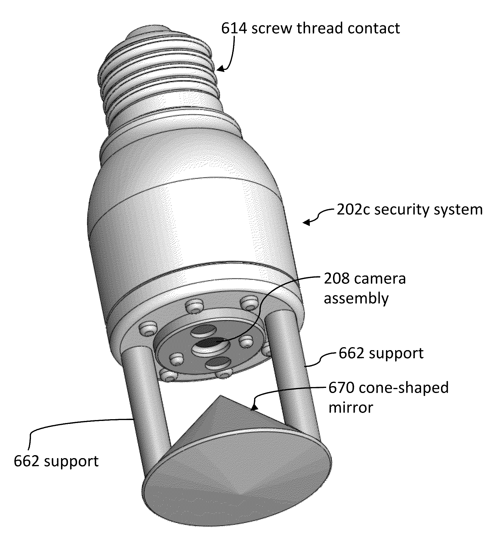
[0025]The camera can be located at the distal end of the outer housing. The camera can be oriented such that the camera faces away from the foot contact. The security system can further include a cone-shaped mirror coupled to the distal end of the security system such that a tip of the cone-shaped mirror faces the camera and faces towards the foot contact. The cone-shaped mirror can enable the camera to see a field of vision that covers at least 330-degrees.
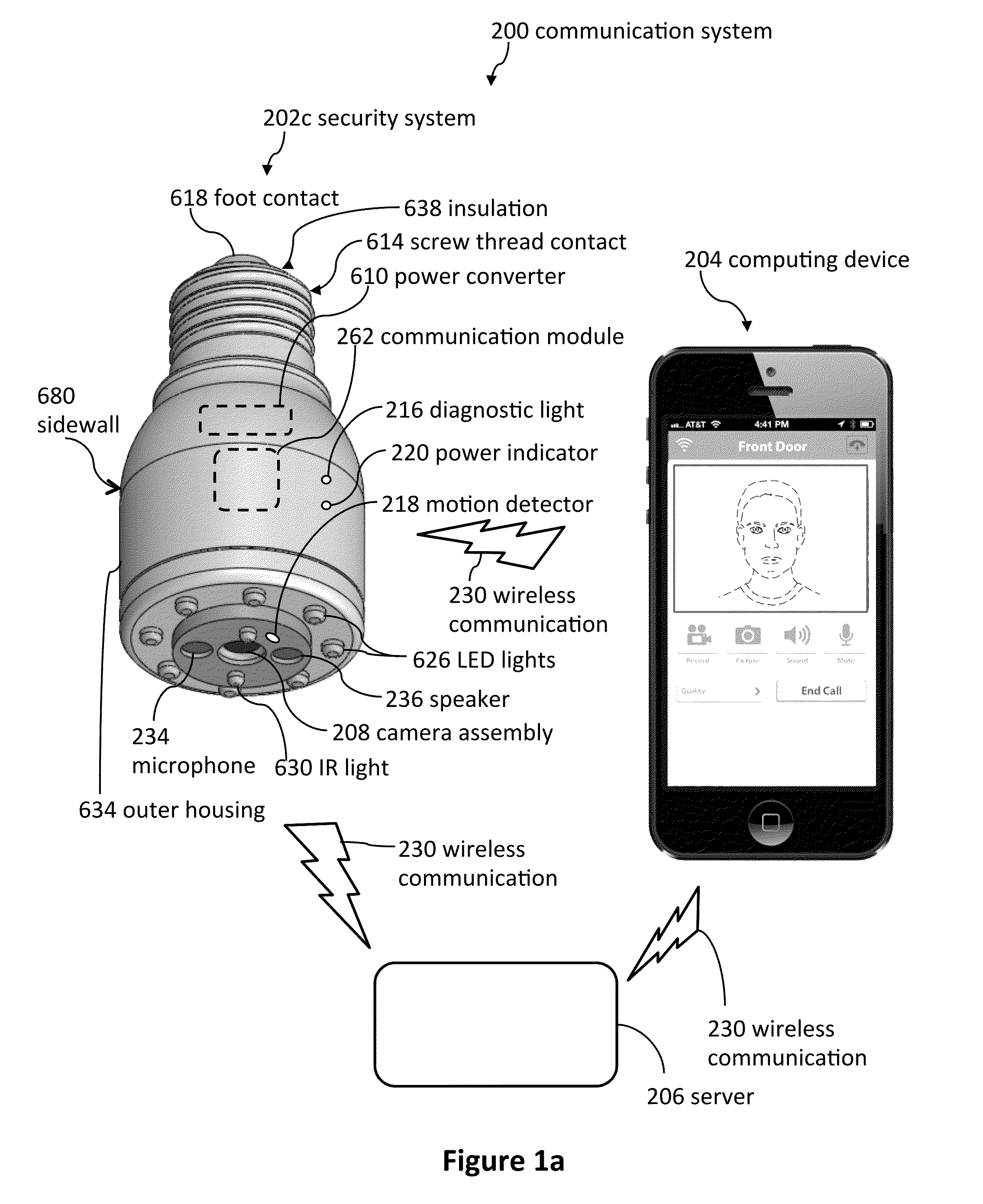
[0026]The outer housing of the security system can be sealed such that the speaker, microphone, and communication module are protected from moisture and contaminants.

Problems solved by technology

Furthermore, video cameras often require electrical power.

Method used


Image

  • Light socket cameras
  • Light socket cameras
  • Light socket cameras

Examples


Embodiment Construction

[0047]Although certain embodiments and examples are disclosed below, inventive subject matter extends beyond the specifically disclosed embodiments to other alternative embodiments and / or uses, and to modifications and equivalents thereof. Thus, the scope of the claims appended hereto is not limited by any of the particular embodiments described below. For example, in any method or process disclosed herein, the acts or operations of the method or process may be performed in any suitable sequence and are not necessarily limited to any particular disclosed sequence. Various operations may be described as multiple discrete operations in turn, in a manner that may be helpful in understanding certain embodiments; however, the order of description should not be construed to imply that these operations are order dependent. Additionally, the structures, systems, and / or devices described herein may be embodied as integrated components or as separate components.

[0048]For purposes of comparing...


PUM


Abstract

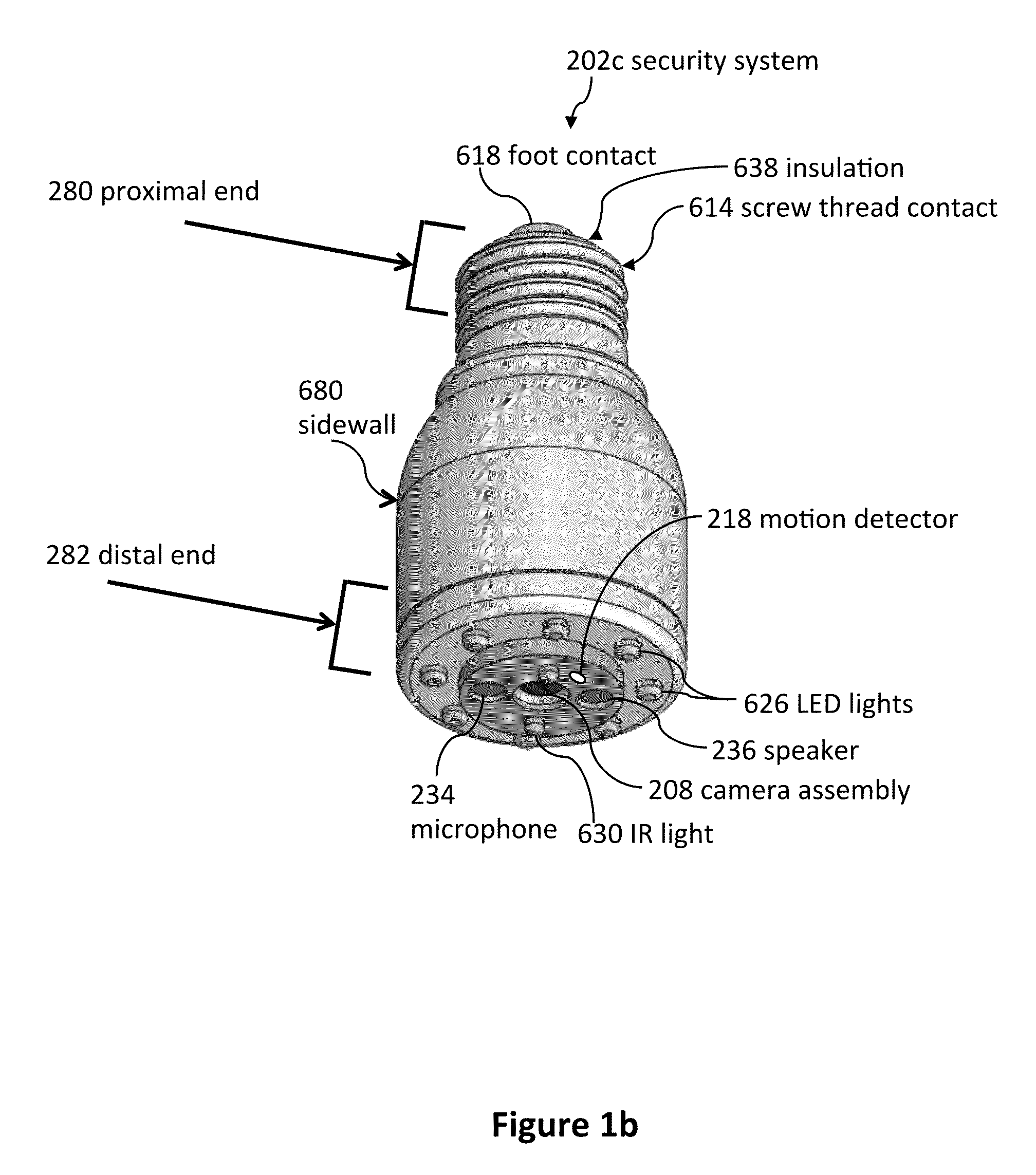
Security systems can be used to detect a visitor. The security system can include a camera that is configured to take a video of the visitor. As well, the security system can be configured to transmit the video of the visitor to a remote computing device. The video of the visitor can be displayed on the remote computing device. The security system can be attached to a light socket.

Description

CROSS-REFERENCE TO RELATED APPLICATIONS[0001]This application claims the benefit of and is a continuation-in-part of Nonprovisional patent application Ser. No. 14 / 469,583; filed Aug. 27, 2014; and entitled SMART LOCK SYSTEMS AND METHODS; the entire contents of which are incorporated herein by reference. U.S. Nonprovisional patent application Ser. No. 14 / 469,583 claims the benefit of U.S. Provisional Patent Application No. 61 / 872,439; filed Aug. 30, 2013; and entitled DOORBELL COMMUNICATION SYSTEMS AND METHODS; the entire contents of which are incorporated herein by reference. U.S. Nonprovisional patent application Ser. No. 14 / 469,583 claims the benefit of and is a continuation-in-part of U.S. Nonprovisional patent application Ser. No. 14 / 099,888; filed Dec. 6, 2013; and entitled DOORBELL COMMUNICATION SYSTEMS AND METHODS, which issued as U.S. Pat. No. 8,823,795 on Sep. 2, 2014; the entire contents of which are incorporated herein by reference. U.S. Nonprovisional patent application ...

Claims


Application Information

Patent Timeline
Patent Type & Authority Patents(United States)
IPC IPC(8): H04N7/18H04M1/02H04N5/232G08B13/196H04N9/47H04M11/00H04M11/02H04M1/725H04M1/72412H04M1/72418
CPCH04M1/0291H04M11/00H04M11/025H04N5/23238H04N7/183G08B13/19632H04N7/186H04N7/188G08B13/19602G08B13/19684H04M1/7253H04M1/72536H04M1/72418H04M1/72412H04N23/50H04N23/698
Inventor SCALISI, JOSEPH FRANK
Owner SKYBELL TECH IP LLC
Why Eureka
Try Eureka