

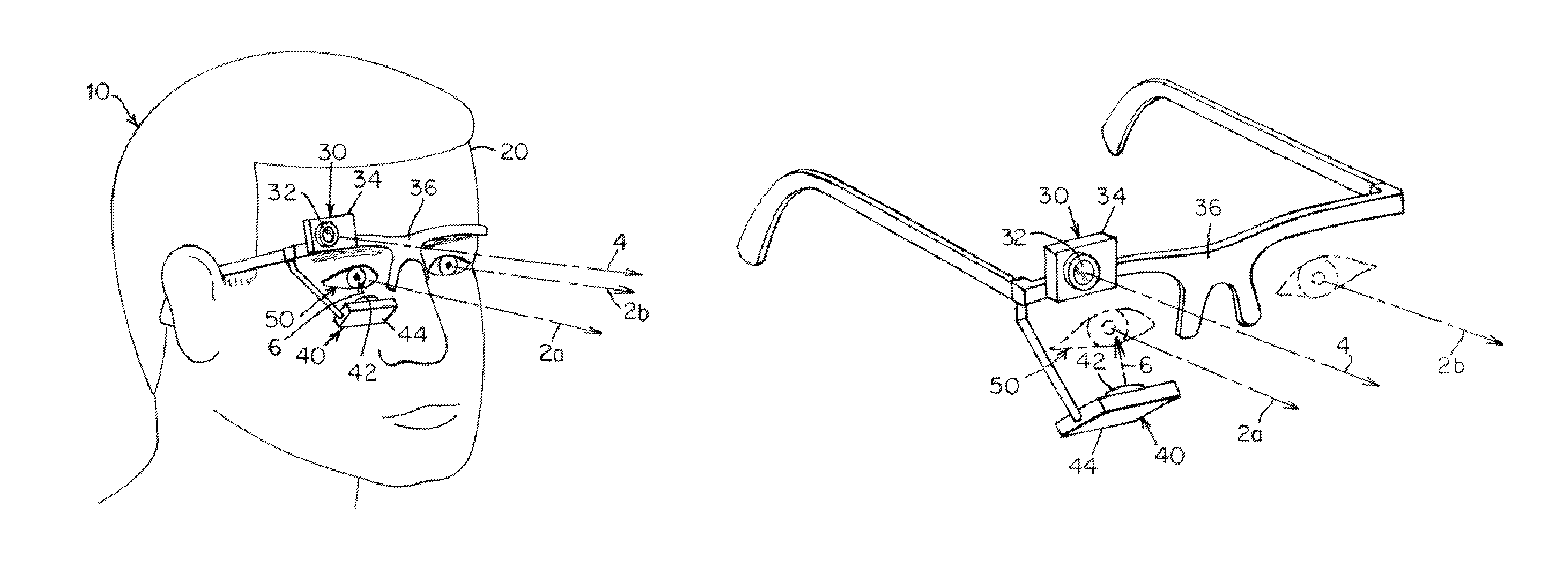
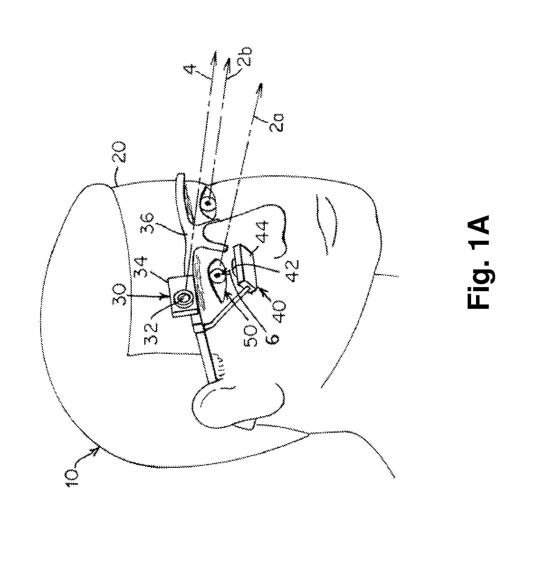
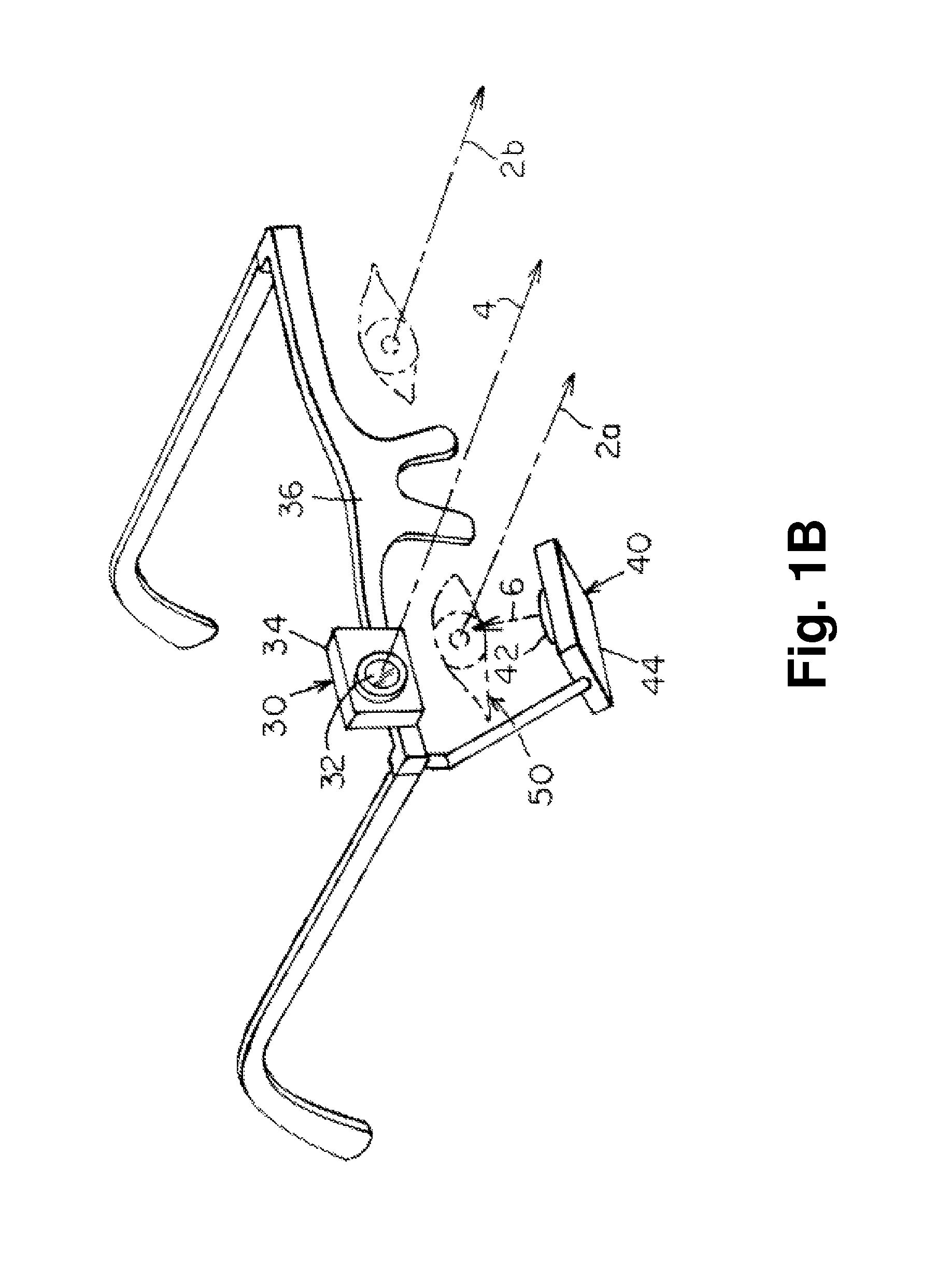
Mobile eye tracking system
a technology of eye tracking and eye camera, which is applied in the field of eye tracking systems, can solve the problems of reducing accuracy, affecting the accuracy of eye tracking devices,
- Summary
- Abstract
- Description
- Claims
- Application Information
AI Technical Summary
Benefits of technology
Problems solved by technology
Method used
Image

Examples
example one
[0110]Two Logitech Webcam Pro 9000 cameras having USB connections were used for both the eye camera and the scene camera. Logitech Quickcam Pro 9000 cameras may be used, but the Webcam Pro 9000 was observed to have a greater ability to focus at a closer distance to the eye compared to the Quickcam Pro 9000. Higher resolution images could be captured of the pupil when the camera is closer to the eye with the Webcam Pro 9000—hence, more accurate estimations of the center of the pupil can be determined. The cameras were stripped down so that they would be as light as possible. The infrared blocking filter of the cameras was replaced with infrared passing filters (Kodak 87 Wratten filter). Hot-swappable filters were also used for both the scene and eye cameras so that each camera was quickly able to switch between visible and infrared light spectrums. The scene camera was attached to a safety glasses frame with heat shrink at a distance of approximately 3.8 cm from the eye. The eye came...
PUM
 Abstract
Description
Claims
Application Information