Foveated display eye-tracking system and method

a technology of eye-tracking system and foveal position, which is applied in the field of foveal position eye-tracking system and method, can solve the problems of shortening the overall ability of the eye-tracking system to facilitate widespread use of this technology for training, requiring extensive image processing methods, and contemporary eye-tracking devices falling short of perfection. , to achieve the effect of simple recording of the foveal position

Inactive Publication Date: 2011-01-18
MITCHELL BRIAN T
View PDF133 Cites 40 Cited by
  • Summary
  • Abstract
  • Description
  • Claims
  • Application Information

AI Technical Summary

Benefits of technology

[0015]Rather than explicitly measuring the position or orientation of the eye, the foveated display eye-tracker invention (FD eye-tracker) relies on a control strategy that works in concert with the head-eye control mechanism to move a foveated region on a computer screen. The idea is that the foveated display provides the same mechanism for acquiring visual information as the Human Vision System (HVS); a region of high-resolution must be sequentially moved around in the field of view at a rapid rate so that the human can obtain a complete understanding of the scene. By combining this approach with the natural head-eye control system of the Human Vision System, a device can be produced that would allow simple recording of the foveal position. Such a device would mirror the mechanism that the HVS uses to collect information, and would be controlled by an augmented version of the HVS head-eye control system.

Problems solved by technology

Although current methods of eye-tracking have demonstrated tremendous potential for the use of this data, they have fallen short in their overall ability to facilitate widespread use of this technology for training.
Many of these methods capture and process a video stream of the working eye, and require extensive image processing methods to obtain eye position information.
Unfortunately, these contemporary eye-trackers fall short of perfection, and as a result, they have received much criticism: they are too expensive, they are too difficult or cumbersome to wear, they are too hard to use, a chin rest or bite bar may be required to restrict head movement, they do not work for individuals that wear glasses or contact lenses, they require frequent calibrations and recalibrations, and the data they collect can be corrupted by blinks or glances.
In short, current eye-tracking methods are far from perfect, and none of the current devices completely satisfy all the requirements identified for an ideal eye-tracker.
In general, this method of eye-tracking requires an infrared emitter and a video camera mounted to maintain a fixed relationship to the subject's eye that often results in cumbersome and expensive eye-tracking devices.
In general, this method of eye-tracking requires goggles with mounted infrared emitters and detectors, and such devices are often both intrusive and expensive.
This method has good spatial resolution and high temporal resolution, but is better for measuring horizontal than vertical eye movements and has difficulty with eye blinks which alter the amount of reflected light.
In general, this method of eye-tracking requires extensive calibration and lacks the precision needed for many eye-tracking applications.
Widespread application of such displays has been slowed by several difficulties.
The technique requires fast and continuous tracking of the gaze point, and previous eyetrackers have been too expensive for widespread application, too imprecise, or too invasive for routine use.

Method used


Image

  • Foveated display eye-tracking system and method
  • Foveated display eye-tracking system and method
  • Foveated display eye-tracking system and method

Examples


Embodiment Construction

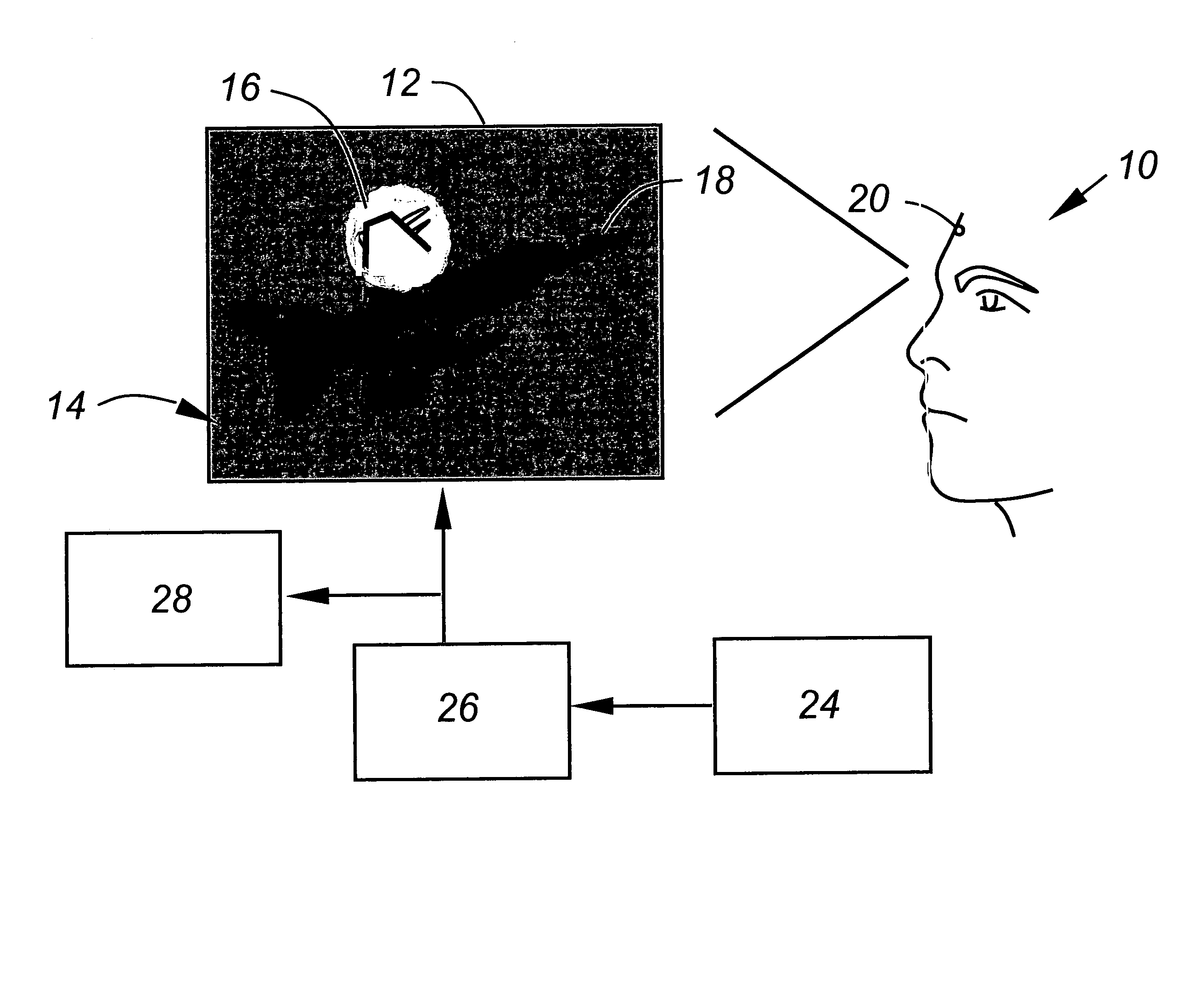
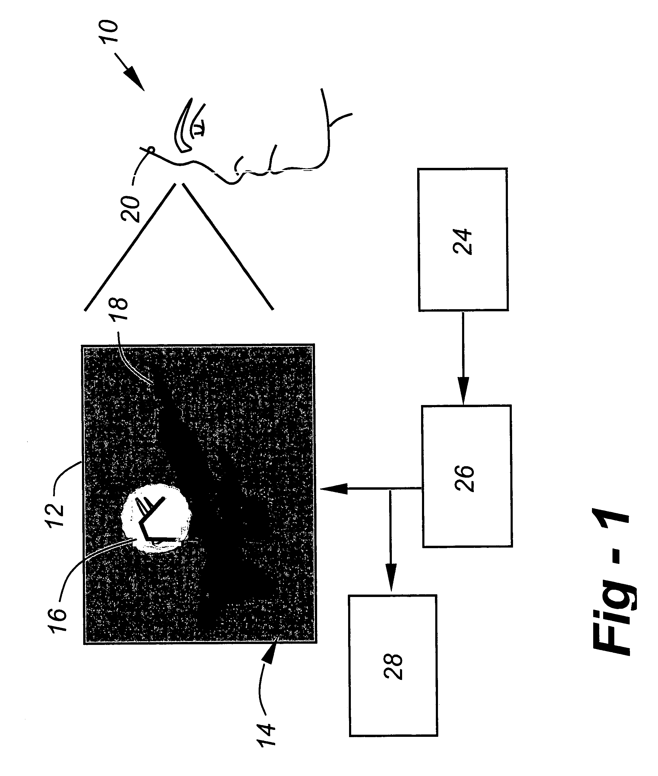
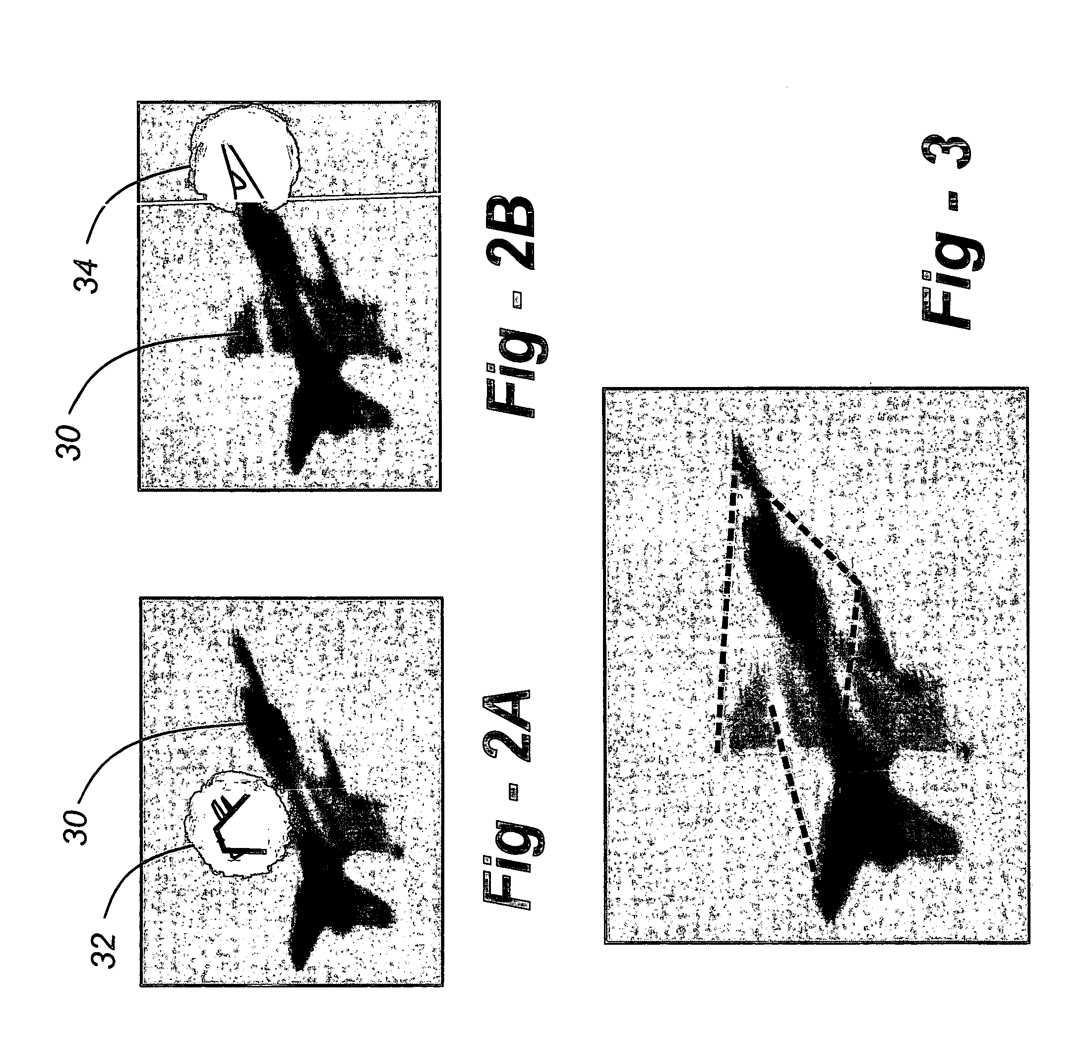
[0020]FIG. 1 is a schematic drawing of a subject generally indicated at 10, using the system of the present invention by observing a foveated display on a screen 12 such as a computer display screen. The image 14 displayed on the screen 12 has an area 16 that is in-focus and other areas 18 that are blurred. In the preferred embodiment, the foveated region 16 is circular in shape to correspond to the human retina. The subject 10 is positioned and directed so that the movement of the eyes to acquire visual information from the foveated image 14 is achieved by motions of the head which move the area 16.

[0021]The subject's head has a motion transmitter 20 attached. The signals generated by the transmitter 20 as the head moves, are picked up by a wireless receiver 24. The output of the receiver is provided to a foveated display generator 26. The foveated display generator 26 produces the image 14 with an in-focus area 16 surrounded by areas 18 that are blurred and moves the in-focus area...


PUM


Abstract

A system for detecting and recording eye-tracking data by presenting to an observer a display image with an area in focus surrounded by blurred areas. The observer may shift the focus area within the image by head movements which are wirelessly transmitted to a receiver and used to modify the displayed image. This system solves that part of the eye-tracking problem that is most critical for measuring cognitive processes.

Description

REFERENCE TO RELATED APPLICATION[0001]This application claims priority from U.S. Provisional Patent Application Ser. No. 60 / 470,940, filed May 15, 2003, the entire content of which is incorporated herein by reference.FIELD OF THE INVENTION[0002]This invention relates to a system and method for analyzing and recording the eye movement of a subject exposed to a display of an image, and more particularly, to such a system in which the display image has a foveated region and a non-foveated region and the system detects head movement of the subject to move the foveated region within the image.BACKGROUND OF THE INVENTION[0003]There is little doubt that eye-tracking provides valuable insight into the current mental state and problem solving strategy of a human subject. The human retina is anisotropic, and has a high-resolution fovea surrounded by a much lower resolution peripheral retina. In order for this architecture to work properly, the eyes must move rapidly about the scene. The net e...

Claims


Application Information

Patent Timeline
Patent Type & Authority Patents(United States)
IPC IPC(8): G09G3/06G06F3/033A61B3/113A61B5/0496A61B5/11G02B27/00G06F3/01G09G5/00
CPCA61B3/113A61B5/6814G02B27/0093G06F3/013A61B5/0496A61B5/11A61B5/398G06V40/19A61B5/163
Inventor MITCHELL, BRIAN T.
Owner MITCHELL BRIAN T
Why Eureka
Try Eureka