
Memory device

a memory device and memory technology, applied in the direction of electrical apparatus construction details, coupling device connections, support structure mounting, etc., can solve the problems of difficult storage or mailing of memory devices, which are usually not possible, and achieve the effect of convenient storage or mailing

Inactive Publication Date: 2006-11-14
FREECOM TECH
View PDF15 Cites 54 Cited by
  • Summary
  • Abstract
  • Description
  • Claims
  • Application Information

AI Technical Summary

Benefits of technology

"The patent describes a flat memory card with a USB connector positioned entirely within the card for protection. The connector can be easily inserted into a computer port without interfering with other ports. The card can be easily stored or mailed and is designed to be used as a storage medium for multimedia appliances. The technical effects of this design include improved protection and portability of the memory device."

Problems solved by technology

One drawback of the known memory device is the fact that, due to the selected shape of the housing, it is usually not possible, for example in the case of computers having two more USB ports positioned adjacently to each other, to connect two memory devices to said slots at the same time.
In addition, the housing of the known memory device makes it difficult to simply store or mail the memory device.
In the position of rest the connection side of the USB connector is accessible from the outside so that the connector can easily be damaged and / or dirt can cause malfunctioning.

Method used


Image

  • Memory device
  • Memory device
  • Memory device

Examples


Embodiment Construction

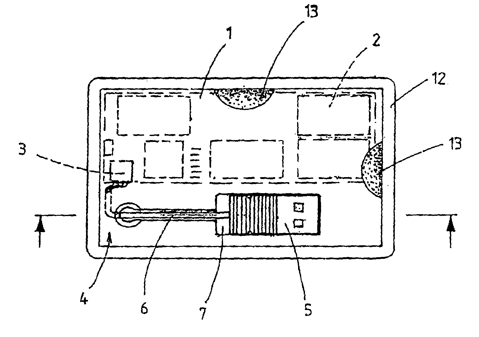
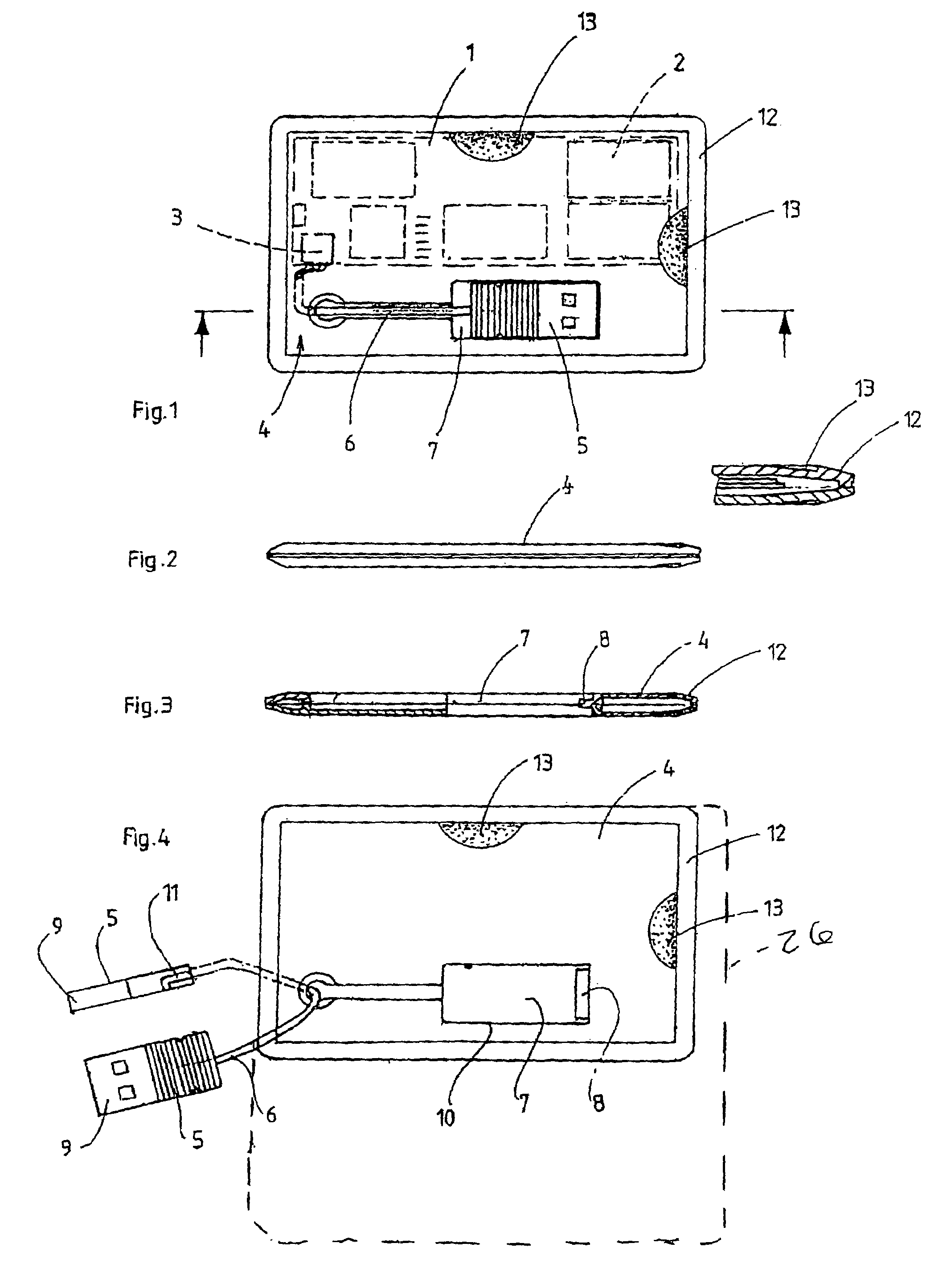
[0015]FIGS. 1–4 show a memory device, with the top plan view of FIG. 1 illustrating a printed circuit board 1 in a dashed line, on which printed circuit board inter alia a memory chip 2 and a USB controller or interface 3 are present. As appears from FIGS. 1–4, the memory device is in the form of a flat memory card 4 of rectangular shape, which, in the preferred embodiment thereof, has the surface area dimensions of a standard credit card, i.e. about 54×85 mm. The memory card 4 comprises a USB connector 5, by means of which the memory device can be connected to a USB port of a computer (not shown). The USB connector 5 is movable between a position of rest (shown in FIG. 1), in which the USB connector is positioned within the confines of the memory card 4, and an operative position shown in FIG. 4, in which the USB connector projects beyond the perimeter of the memory card 4. In the embodiment that is shown in FIGS. 1–4, the USB connector 5 is connected to the memory card via a cable...


PUM


Abstract

A memory device is provided with a memory chip and a controller, which can be connected to a computer via a USB connector. The memory device is implemented in the form of a flat memory card, wherein the USB connector is movable between a position of rest, in which the connector is accommodated in an opening of the memory card, and an operative position, in which the connector projects beyond the perimeter of the memory card. The opening is a rectangular opening lying entirely within the perimeter of the memory card, wherein in the position of rest the USB connector is positioned entirely within the confines of the memory card.

Description

CROSS-REFERENCE TO RELATED APPLICATION[0001]This Application claims priority and is a continuation application of International Application No. PCT / NL03 / 00104, filed Feb. 13, 2003, published in English.BACKGROUND OF THE INVENTION[0002]The invention relates to a memory device comprising a memory chip and a controller, which can be connected to a computer via a USB (Universal Serial Bus) connector.[0003]Such a memory device is known in various embodiments, in which the housing of the memory device is a rectangular block, a key ring or the like, for example. The USB connector is fixedly connected to the housing of the memory device, and usually a loose protective cap or the like is used for the USB connector to protect the USB connector from damage, dirt and the like. One drawback of the known memory device is the fact that, due to the selected shape of the housing, it is usually not possible, for example in the case of computers having two more USB ports positioned adjacently to each ...

Claims


Application Information

Patent Timeline
Patent Type & Authority Patents(United States)
IPC IPC(8): H05K1/14H05K5/02
CPCG06K19/07732H05K5/026G06K19/07733
Inventor HOOGERDIJK, DIRK CORNELIS
Owner FREECOM TECH
Learn More