Part vision detection device

A visual inspection device and technology for parts, applied in the field of industrial manufacturing, can solve the problems of inability to take into account the measurement of parts shape, inaccurate measurement results, and the influence of human factors, so as to avoid repeated calibration of the system, improve identification capabilities, and facilitate recording. Effect

Inactive Publication Date: 2009-08-19
BEIHANG UNIV
View PDF0 Cites 64 Cited by
  • Summary
  • Abstract
  • Description
  • Claims
  • Application Information

AI Technical Summary

Problems solved by technology

At present, non-contact measurement methods are often used for such small parts. One method is to use the projection method. The light source and the projection screen are placed on both sides of the part to be measured, and the light source emits light to project the shape of the part onto the surface. Zoom in on the projection screen, compare with the standard size on the projection screen, estimate the size, and judge whether the part is qualified. This method is subject to the distance between the part and the light source, whether the central axis of the part is perpendicular to the optical axis of the light source, and the edge of the part image caused by the brightness change of the light source. In addition, this method relies on the human eye to determine the alignment edge, which is also affected by the subjective factors of the operator; another method places the part on the glass plate with a backlight, and requires the operator to observe the engraving of the lens with the human eye. Align the edge of the part with the line and read the corresponding scale, which is also affected by human factors
The surface defect detection of parts often uses microscopic measurement technology. The operator observes the part under a universal tool microscope, and estimates the size of the defect by comparing it with the standard reticle. The measurement result is not accurate enough.
[0003] At present, with the continuous development of machine vision technology, the visual microscopic measurement technology that combines cameras and microscopes has developed rapidly. The local surface is enlarged through the optical system and then imaged on the camera. After the image is digitized, it is automatically recognized and measured by a computer. , which can not only eliminate the interference of subjective factors of inspectors, reduce labor intensity, and improve production efficiency, but also quantitatively describe and count defects, which has incomparable advantages over manual inspection. The surface defect detection of shank spherical parts generally cannot take into account the shape measurement of the parts

Method used


Image

  • Part vision detection device
  • Part vision detection device
  • Part vision detection device

Examples


Embodiment Construction

[0031] The technical solution of the present invention will be further described below in conjunction with the accompanying drawings.

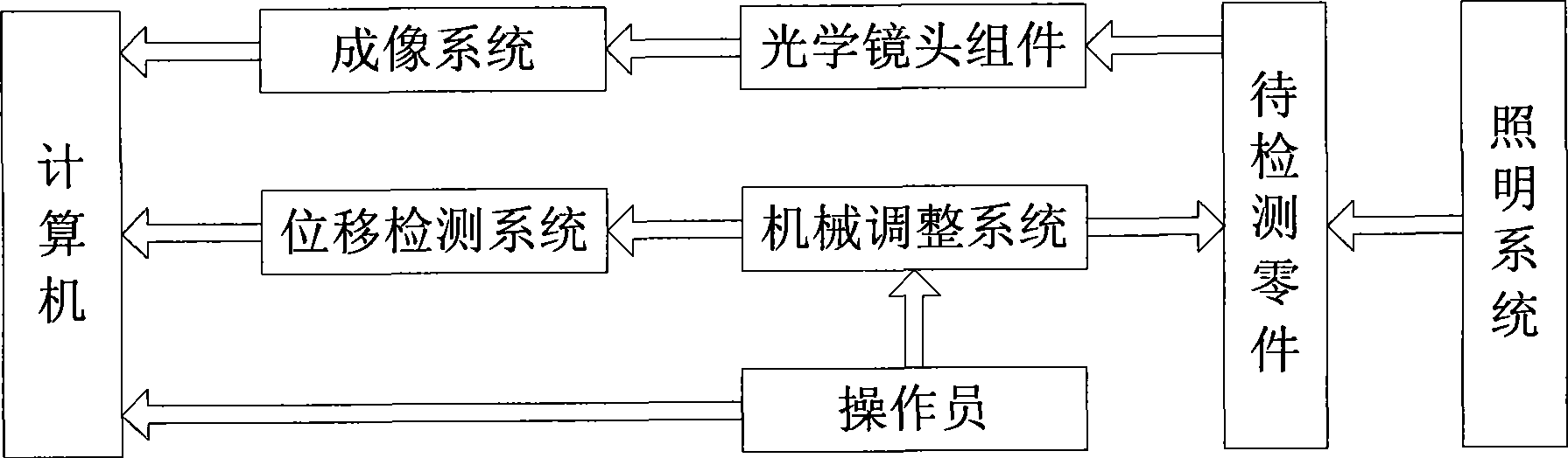
[0032] Such as figure 1 As shown, the present invention includes an imaging system composed of a CCD camera and an image acquisition card, an optical lens assembly composed of a lens body and a magnifying objective lens, an illumination system for shape measurement and surface defect detection, and a translation platform for adjusting the position of parts. The mechanical adjustment system, the displacement detection system to record the moving distance of the displacement platform, and the computer to record and process the image.

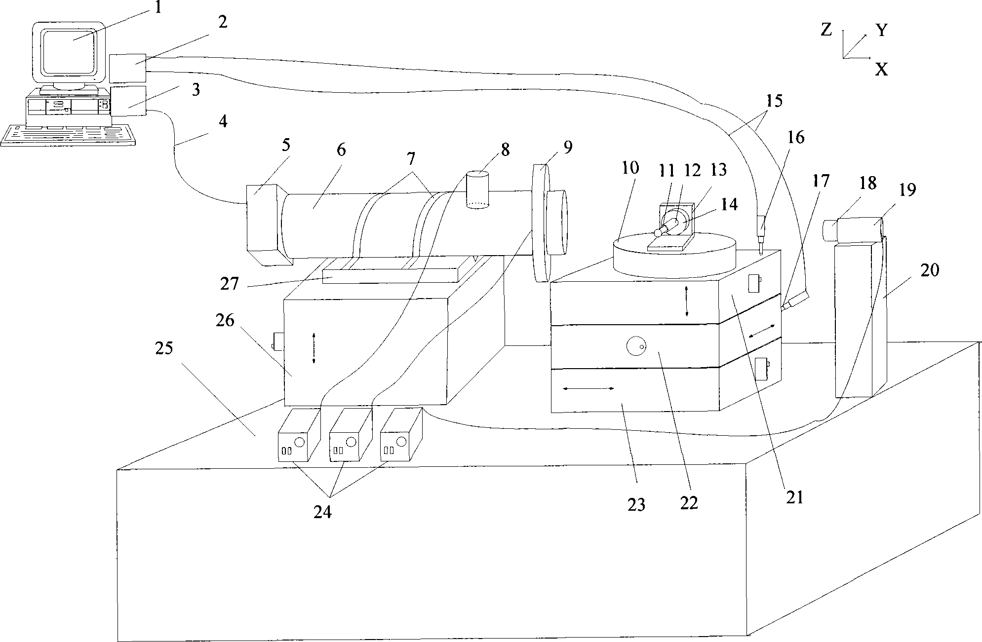
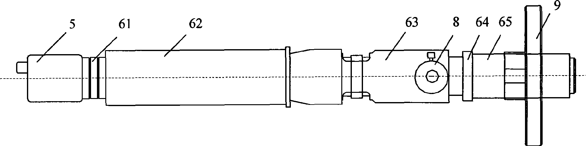
[0033] Such as figure 2 , 3 As shown, the lifting platform 26 is installed on the base 25, the V-shaped groove 27 is installed on the lifting platform 26, the optical lens assembly 6 is fixed on the V-shaped groove 27 by a steel belt 7, placed horizontally, the CCD camera 5 and the optical lens assembly 6 Conn...


PUM


Abstract

A visual detection device for parts mainly comprises an imaging system, an optical lens component, a lighting system, a mechanical adjusting system, a displacement detection system and a computer, wherein the imaging system consists of a CCD camera and an image acquisition card; the optical lens component consists of a lens body, an amplifying objective lens, and the like; the lighting system is respectively used for detecting surface defects and measuring topographic sizes; the mechanical adjusting system consists of displacement platforms used for adjusting the positions of the parts; the displacement detection system is used for recording the displacement distance of the displacement platforms; and the computer is used for recording and processing images. By shooting edge images of theparts through the imaging system and recording the displacement distance of the displacement platforms through the displacement detection system, the detection device calculates the topographic sizessuch as diameter, and the like, detects the surface defects of the whole spherical surface by the combined rotation of rotary tables, measures the defect sizes accurately, records the number of the defects and meets the two detection requirements of topography measurement and surface detection. By utilizing the visual microscopic detection technology, the device has high system resolution, good integrated performance and simple measurement process.

Description

technical field [0001] The invention relates to a part visual detection device, which is used for the visual detection of part shape and surface, especially suitable for the detection of small spherical parts with handles, and belongs to the field of industrial manufacturing. Background technique [0002] Some key spherical parts with shanks in industrial production have small dimensions and a diameter of only a few millimeters. It is very difficult to machine and measure the shape. On the other hand, the requirements for the smoothness of the machined surface are also very high. Defects such as scratches and black spots on the surface have strict requirements in terms of quantity and size. At present, non-contact measurement methods are often used for such small parts. One method is to use the projection method. The light source and the projection screen are placed on both sides of the part to be measured, and the light source emits light to project the shape of the part on...

Claims


Application Information

Patent Timeline
Patent Type & Authority Applications(China)
IPC IPC(8): G01N21/952G01B11/02G01B11/08
Inventor 赵慧洁葛文谦李旭东
Owner BEIHANG UNIV
Why Eureka
Try Eureka