Wave saw blade

Inactive Publication Date: 2005-03-29
NIWA DAIYAMONDO INDS
View PDF9 Cites 41 Cited by
  • Summary
  • Abstract
  • Description
  • Claims
  • Application Information

AI Technical Summary

Benefits of technology

Therefore, the present invention has been made in view of the above problems, and it is an object of the present invention to provide a saw blade which is capable of withstanding the cutting force in the course of cutting

Problems solved by technology

When the shank 11 of the saw blade 10 vibrates widely, the shank 11 may be broken or the cutting tips 14 attached to the outer circumference of the shank 11 may be broken off from the shank 11 of the saw blade 10 with the result that a an accident may be caused, for example, an operator of the saw blade may be injured in the course of cutting the workpiece.
When the impact is applied to a straight shank of the saw blade, the shank vibrates seriously.
However, no clearance is provided at the end part of the outer circumference of the shan

Method used


Image

  • Wave saw blade
  • Wave saw blade
  • Wave saw blade

Examples


Embodiment Construction

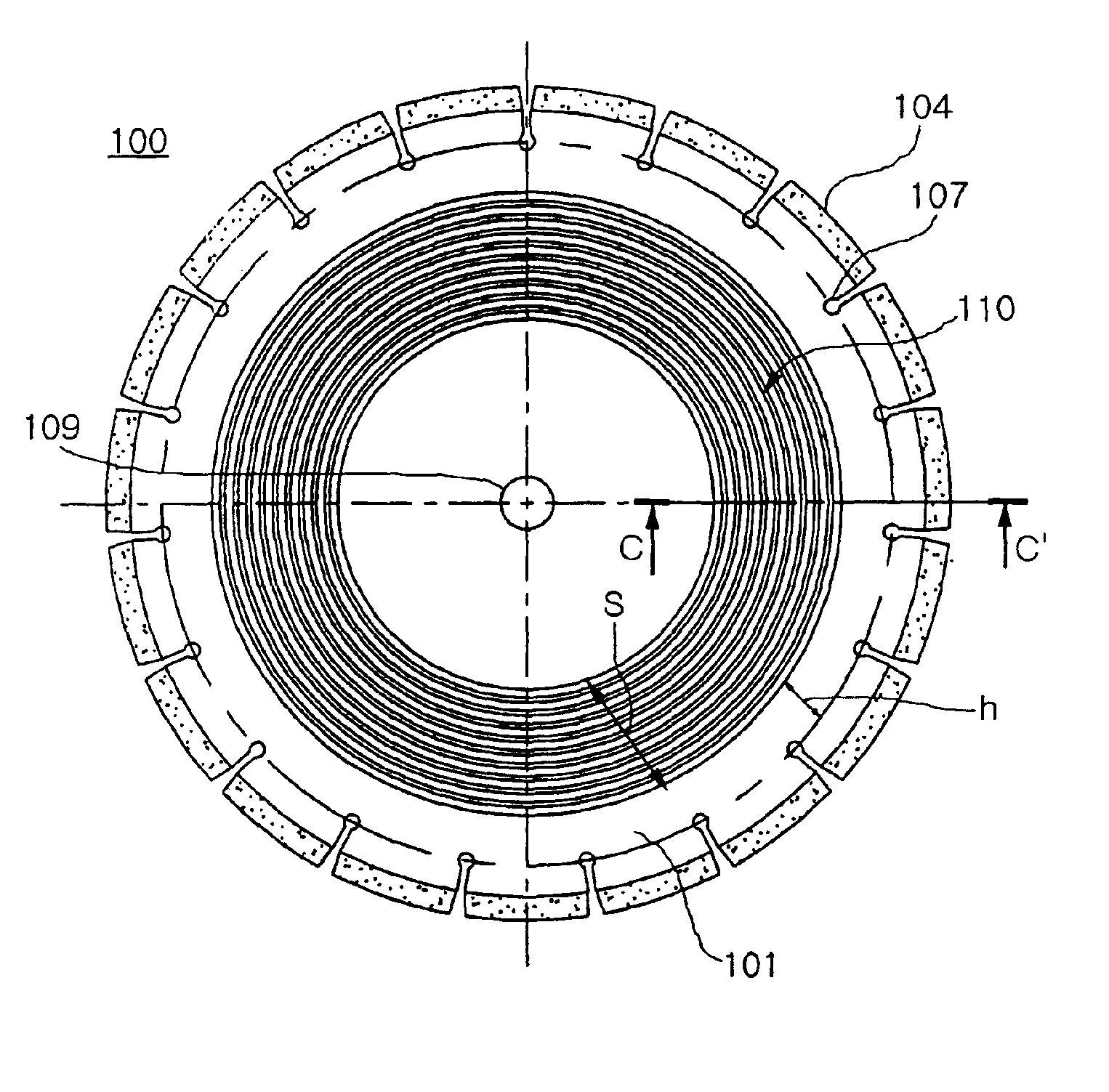
FIG. 5 is a plan view of a saw blade according to a preferred embodiment of the present invention with a plurality of cutting tips of the saw blade attached to a ring-shaped wave shank of the saw blade, and FIG. 6 is a cross-sectional view of the saw blade according to the preferred embodiment of the present invention taken along line C-C′ of FIG. 5.

As shown in FIG. 5, a saw blade 100 of the present invention comprises a shank 101 having wave-shaped portions formed thereon, and a plurality of cutting tips 104 attached to the outer circumference of the shank 101 for cutting a workpiece (not shown). The shank 101 is a disc-shaped shank having a prescribed radius of rotation and a prescribed thickness. The shank 101 is made of prescribed alloy steel. The shank is provided at the center thereof with an insertion hole 109, through which a rotating shaft of a powered tool (not shown) is inserted.

The shank 101 is also provided at the outer circumference thereof with a plurality of spaced s...


PUM

PropertyMeasurementUnit
Shapeaaaaaaaaaa
Radiusaaaaaaaaaa
Heightaaaaaaaaaa

Abstract

A saw blade for cutting hard workpieces, such as concrete or stone, characterized by improvement of the shape of a shank of the saw blade providing a plurality of cutting tips of the saw blade with a rotational force while the cutting tips are securely attached to the shank. The saw blade comprises a disc-shaped shank having an insertion hole formed at the center thereof, through which a rotating shaft of an electric-powered tool is inserted, and wave-shaped portions formed over a prescribed portion of the radius of the disc-shaped shank, and a plurality of cutting tips attached to the outer circumference of the shank for cutting a workpiece. The wave-shaped portions are spaced a prescribed distance from each other and alternately arranged on the front and rear surfaces of the disc-shaped shank. The prescribed portion of the radius of the disc-shaped shank is at a distance from the center of the insertion hole. The cutting tips contain particles of high hardness.

Description

BACKGROUND OF THE INVENTION1. Field of the InventionThe present invention relates to a saw blade for cutting hard workpieces, such as concrete or stone, and more particularly to a saw blade comprising a shank and a plurality of cutting tips attached to the outer circumference of the shank, characterized by improvement of the shape of the shank of the saw blade providing the cutting tips of the saw blade with a rotational force while the cutting tips are securely attached to the shank.2. Description of the Related ArtAs well known to those skilled in the art, a saw blade for cutting workpieces generally comprises a shank of a prescribed diameter and a plurality of cutting tips attached to the outer circumference of the shank. Usually, each of the cutting tips is made of a super-abrasive material which has very high hardness, such as diamond or cubic boron nitride (CBN). The cutting tip may be classified as either a segment-type cutting tip or a rim-type cutting tip, on the basis of t...

Claims


Application Information

Patent Timeline
IPC IPC(8): B28D1/12B28D1/02B23D61/02B23D61/04B24D3/00B24D5/06B24D5/12B28D1/04
CPCB28D1/121B28D1/04
Inventor LEE, SEUNG WEONPARK, YONG HYUNCHOI, JONG SUKJUNG, EUI SEOK
Owner NIWA DAIYAMONDO INDS
Why Eureka
Try Eureka