
Remote control and tactile feedback system and method for medical apparatus

a technology of remote control and tactile feedback, applied in mechanical equipment, valves, operating means/releasing devices, etc., can solve the problems of difficult or impossible to obtain this type of feedback information, affecting the clinical practice, and reducing the fineness of the control of breathing gas supply and the sensing of lung or other respiratory conditions affecting the subject, etc., to achieve the effect of not easily simulated in the field or classroom

Inactive Publication Date: 2010-03-02
DATEX OHMEDA
View PDF25 Cites 41 Cited by
  • Summary
  • Abstract
  • Description
  • Claims
  • Application Information

AI Technical Summary

Benefits of technology

This system reduces training time for clinicians, allows for effective control and sensing of patient conditions without fatigue, and enables flexible operation around patients, improving care by providing real-time tactile feedback and control of ventilator functions.

Problems solved by technology

It is difficult or impossible to obtain this type of feedback information when mechanical ventilating apparatus provides the breathing gases.
However, if bagging is carried out for a long time, it becomes fatiguing to the clinician lessening both the fineness of the control of breathing gas supply and the sensing of lung or other respiratory conditions affecting the subject.
Current practice unfortunately requires the caregiver to acquire several years of experience manually ventilating patients having different respiratory ailments in order to develop a sufficient understanding as to how to operate the device.
Additionally, unique lung diseases may call for unusual practice that is not easily simulated in the field or classroom.

Method used


Image

  • Remote control and tactile feedback system and method for medical apparatus
  • Remote control and tactile feedback system and method for medical apparatus
  • Remote control and tactile feedback system and method for medical apparatus

Examples


Embodiment Construction

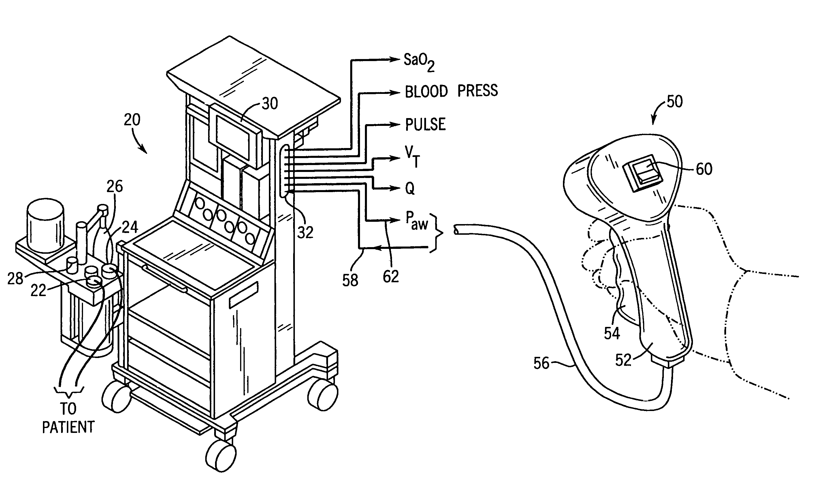
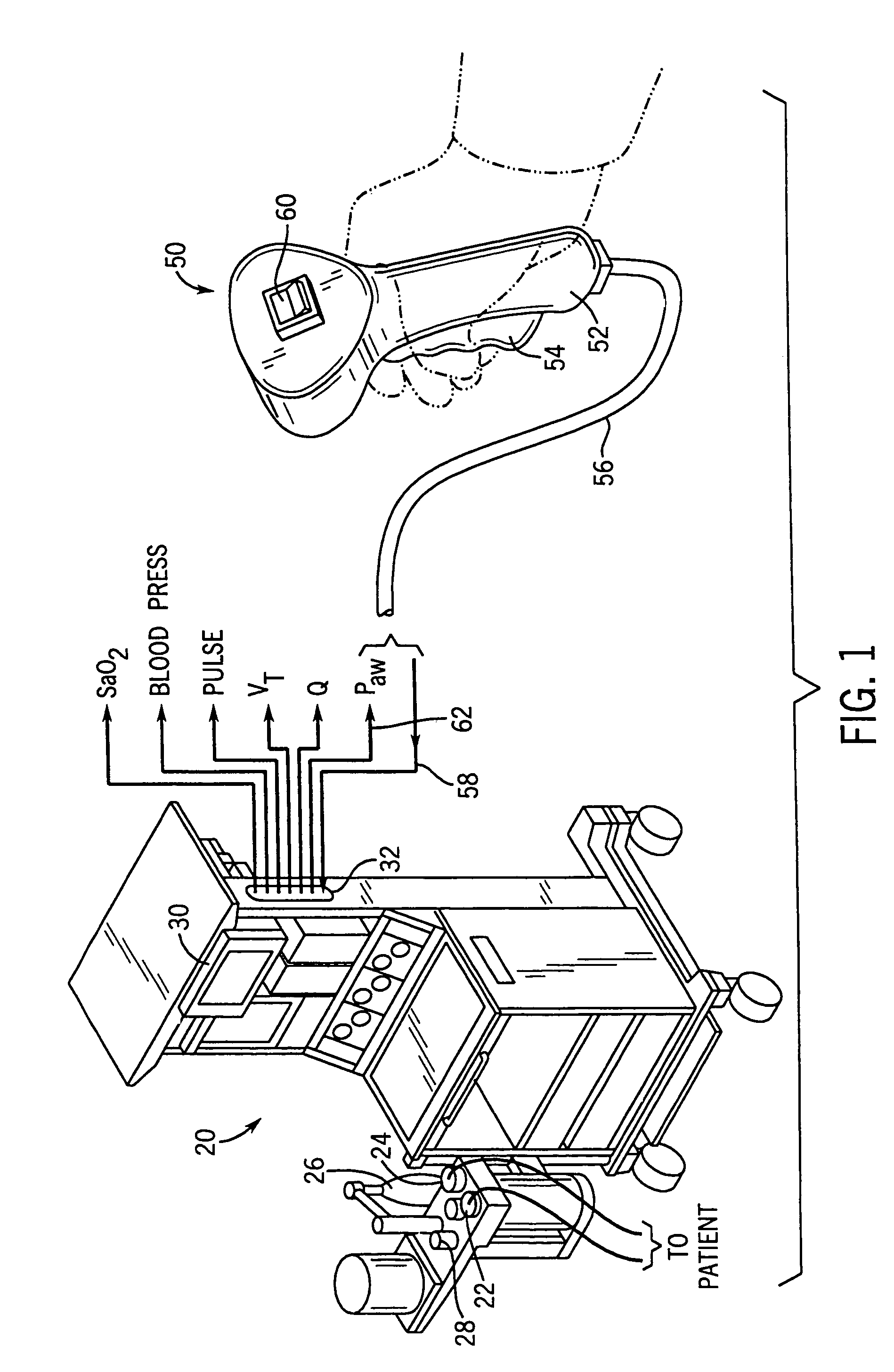
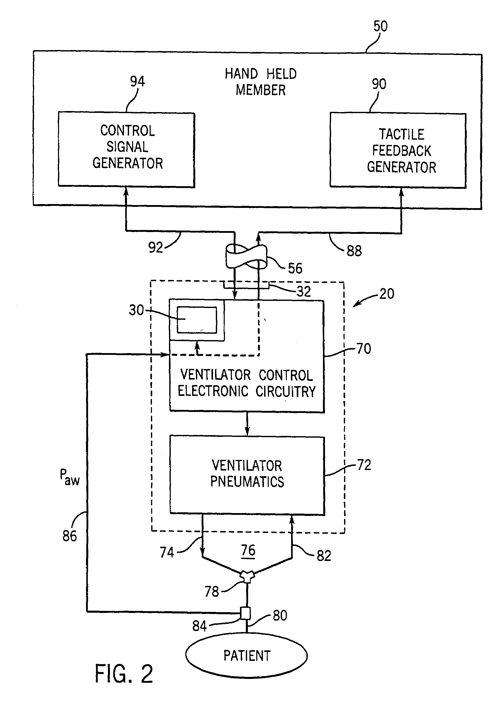
[0039]Medical apparatus suitable for use with the system of the present invention is shown in FIG. 1 as ventilator 20 incorporated in an anesthesia machine. Ventilator 20 has connectors 22 and 24 suitable for connection to the inspiratory and expiratory limbs of a breathing circuit leading to a patient, as diagrammatically shown in FIG. 1. Ventilator 20 provides breathing gases to the patient in the inspiratory limb of the breathing circuit and receives gases expired by the patient in the expiratory limb.

[0040]Ventilator 20 is provided with bag 26 for manually bagging the patient. Switch 28 is operated to allow bag 26 to provide breathing gases to the patient.

[0041]Ventilator 20 receives inputs from sensors associated with the patient and / or ventilator 20. The data contained in these inputs may be displayed on patient monitor 30. Data relating to the sensed parameters is also provided to terminal 32. Typical data outputs are shown as patient airway pressure Paw, tidal volume VT, bre...


PUM


Abstract

A system and method are for monitoring control signals provided to a medical apparatus bases upon tactile feedback from the apparatus. The system and method employ a monitoring signal indicative of a parameter relating to the apparatus or to a condition of a patient associated with the apparatus. The system includes a first feedback device in communication with the apparatus and arranged to provide tactile feedback to a first individual based upon the monitoring signal; a first controller actuatable by the first individual to provide a control signal to the apparatus for carrying a control action in the apparatus; a second feedback device in communication with the apparatus and arranged to provide tactile feedback to a second individual based upon the monitoring signal from the apparatus; and a second controller in communication with the first controller such that the control signal given by the first individual to the first controller is reflected in the second controller and communicated to the second individual. The first feedback device, first controller, second feedback device and second controller are in communication with the apparatus such that the first and second individual can be distant from the apparatus and patient and move about the apparatus and patient to a desired location.

Description

CROSS REFERENCE TO RELATED APPLICATION[0001]This application is a continuation-in-part of application Ser. No. 09 / 924,148, filed Aug. 7, 2001, U.S. Pat. No. 6,834,647.BACKGROUND OF THE INVENTION[0002]The present invention relates to a system providing remote control to medical apparatus, such as a respiratory ventilator for a patient. The system also provides a tactile expression of a parameter relating to a patient or a medical apparatus to a user of the apparatus. For example, the system may provide a tactile indication of a breathing characteristic of a patient connected to a ventilator to a clinician using the system.[0003]In one aspect of the system of the present invention, a manual member has a handle with a moveable, trigger-like member. The handle and trigger are gripped by the user. When the trigger is squeezed by the user, a signal generator is operated to provide a control signal, through a cable or other suitable means, to the ventilator for use in controlling the appar...

Claims


Application Information

Patent Timeline
Patent Type & Authority Patents(United States)
IPC IPC(8): F16K31/02A61M16/00
CPCA61M16/0051A61M2205/3561A61M2205/3576A61M2205/505A61M2209/01A61M16/024Y10S128/903Y10S128/904Y10S128/905Y10S128/92
Inventor RICK, NORMAN A.TOBIA, RONALD L.
Owner DATEX OHMEDA
Learn More