Exhaust emission purifying apparatus

a technology of exhaust gas and purification apparatus, which is applied in mechanical apparatus, machines/engines, separation processes, etc., can solve the problems of difficult to suitably design the layout of on-vehicle components, and achieve the reduction of the number of components needed, facilitate the determination of the layout of on-vehicle components, and improve the efficiency of the reduction catalyst

Active Publication Date: 2008-06-05
VOLVO LASTVAGNAR AB
View PDF7 Cites 39 Cited by
  • Summary
  • Abstract
  • Description
  • Claims
  • Application Information

AI Technical Summary

Benefits of technology

[0008]With the above-mentioned necessities in view, an object of the present invention is to provide a more compact exhaust emission purifying apparatus equipped with both of the NOx removal function performed by the SCR and the PM collection function.
[0013]According to the exhaust emission purifying apparatus of the present invention, since the nozzle, the reduction catalyst and the filter are appropriately disposed in the exhaust passage which is folded in its direction at least once to have a configuration such that a plurality of layered passage is folded in multi-layers inside the casing, this folded configuration of the exhaust passage allows the lengthwise size of the exhaust emission purifying apparatus which occupies that of the exhaust system to be reduced, and facilitates determination of the layout of on-vehicle components.
[0014]Further, since the nozzle is disposed on the exhaust upstream side in the folded passage portion, which is defined as the portion where the folding of the exhaust passage occurs, it is possible to obtain a desired distance from the reduction catalyst which is disposed on the exhaust downstream side of the folded passage portion. Accordingly, it is possible to obtain a suitable distance and time for achieving the uniform diffusion of the reducing agent or the precursor thereof in the exhaust emission and / or the hydrolysis of the same, before the reducing agent or the precursor thereof which is injected from the nozzle into the exhaust emission reaches the reduction catalyst.
[0015]Further, when the oxidation catalyst is disposed in the exhaust passage on the exhaust upstream side of the nozzle, reduction efficiency at the reduction catalyst can be improved by means of the oxidation effect of the NO achieved by the oxidation catalyst. Alternatively, the filter which is used to collect the PM may also be configured to have the function of the NO oxidation catalyst and disposed on the exhaust upstream side of the nozzle. This allows reduction in the number of components necessary for the exhaust emission purifying apparatus.
[0016]In addition, when the oxidation catalyst is disposed in the exhaust passage at a position located on the exhaust downstream side of the reduction catalyst, exhaustion of the excess reducing agent passing through the reduction catalyst can be prevented by means of the oxidation effect achieved by the oxidation catalyst. Alternatively, the filter which is used to collect the PM may also be configured to have the function of the reducing agent oxidation catalyst and disposed on the exhaust downstream side of the reduction catalyst. This allows reduction in the number of the components necessary for the exhaust emission purifying apparatus.

Problems solved by technology

In addition to this in-series arrangement of the reduction catalyst and the nozzle, if there is needed to further dispose a filter for trapping particulate matters (PM) suspended in the exhaust emission, a lengthwise size of the exhaust emission purifying apparatus which occupies that of the exhaust system becomes larger making it difficult to suitably design layout of on-vehicle components.

Method used


Image

  • Exhaust emission purifying apparatus
  • Exhaust emission purifying apparatus
  • Exhaust emission purifying apparatus

Examples


first embodiment

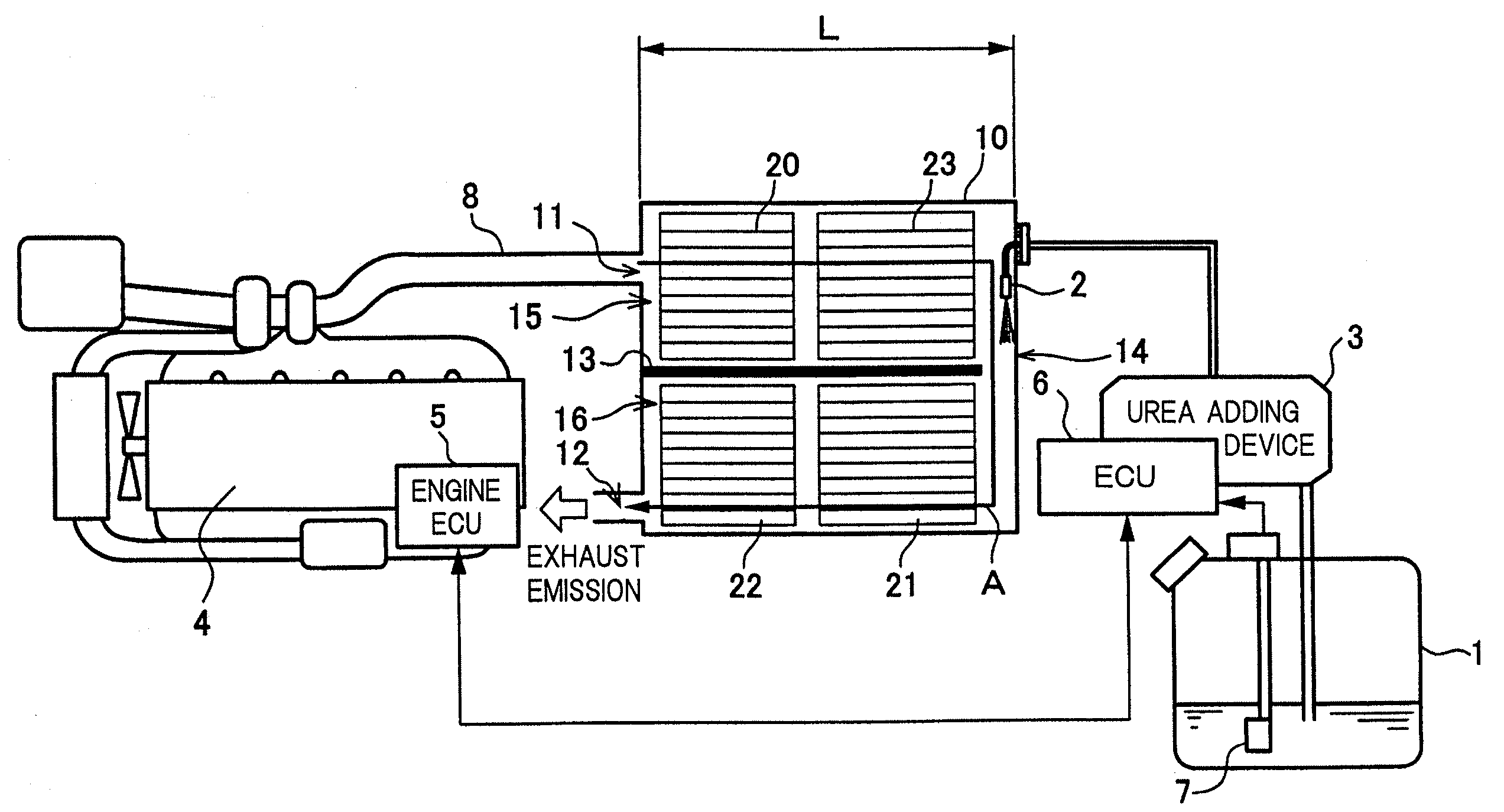
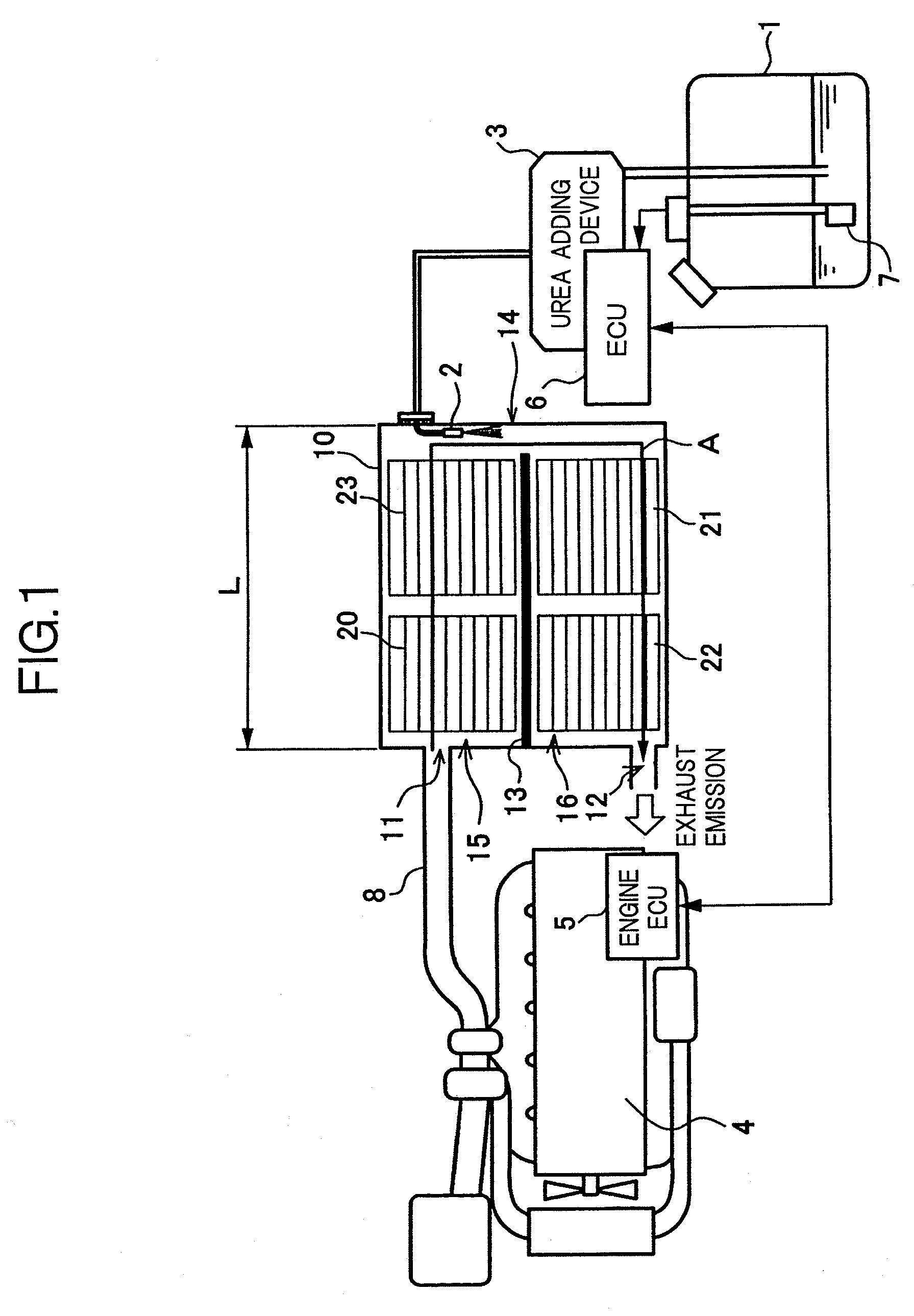
[0031]FIG. 1 shows the casing 10 according to the present invention, in which the oxidation catalyst 20 and the filter 23 are arranged in series in this order along the upstream-to-downstream direction in the upstream-side layered passage 15, which is on the exhaust upstream side of the folded passage portion 14 provided by the compartment wall 13. Whereas, the reduction catalyst 21 and the reducing agent oxidation catalyst 22 are arranged in series in this order along the upstream-to-downstream direction in the downstream-side layered passage 16, which is on the exhaust downstream side of the folded passage portion 14 provided by the compartment wall 13.

[0032]The folded passage portion 14, which gives a passage for turning from the upstream-side layered passage 15 to the downstream-side layered passage 16, has a length substantially corresponding to the height of the casing 10. Consequently, by disposing the nozzle 2 on the exhaust upstream side in the folded passage portion 14, a ...

second embodiment

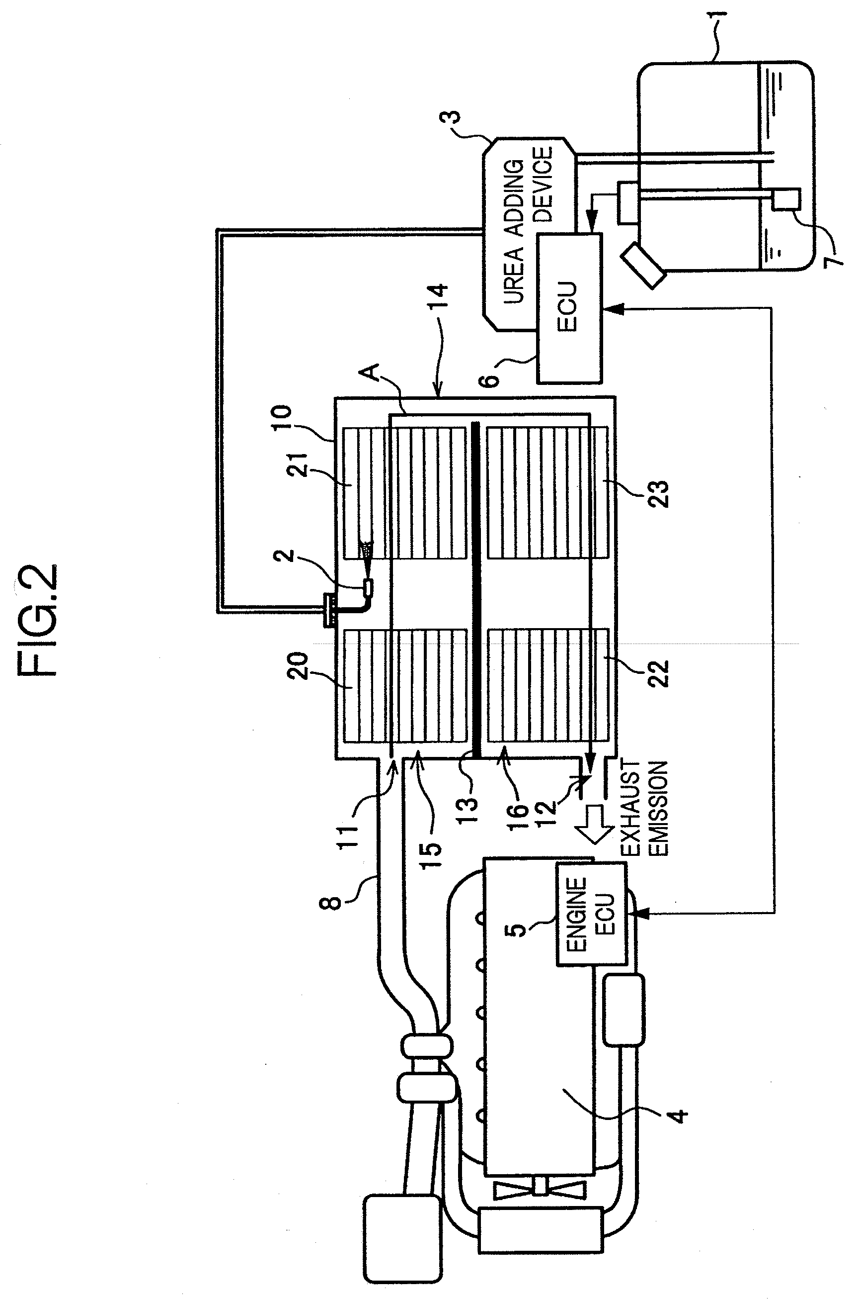
[0033]FIG. 2 shows the casing 10 according to the present invention, in which the oxidation catalyst 20 and the reduction catalyst 21 are arranged in series in this order along the upstream-to-downstream direction in the upstream-side layered passage 15. In the downstream-side layered passage 16, the filter 23 and the reducing agent oxidation catalyst 22 are arranged in series in this order along the upstream-to-downstream direction. The nozzle 2 is disposed between the oxidation catalyst 20 and the reduction catalyst 21 in the upstream-side layered passage 15.

[0034]Regarding the lengthwise size of the exhaust emission purifying apparatus which occupies that of the exhaust system, the second embodiment enjoys similar advantage as do in the first embodiment.

third embodiment

[0035]FIG. 3 shows the casing 10 according to the present invention, in which the oxidation catalyst 20 and the reduction catalyst 21 are arranged in series in this order along the upstream-to-downstream direction in the upstream-side layered passage 15, and the reducing agent oxidation catalyst 22 and the filter 23 are arranged in series in this order along the upstream-to-downstream direction in the downstream-side layered passage 16. The nozzle 2 is disposed between the oxidation catalyst 20 and the reduction catalyst 21 in the upstream-side layered passage 15.

[0036]The third embodiment, in which the position of the reducing agent oxidation catalyst 22 and the filter 23 is arranged in an inverse order to that of the second embodiment, enjoys a similar advantage as do in the second embodiment.

[0037]FIG. 4 shows an example of an arrangement according to a forth embodiment of the present invention, in which a filter 24 whose filtering function is combined with the function of the ox...


PUM

PropertyMeasurementUnit
reactivityaaaaaaaaaa
sizeaaaaaaaaaa
distanceaaaaaaaaaa

Abstract

An exhaust emission purifying apparatus of the present invention has a casing that includes therein a plurality of layered passages which is formed by partitioning an inside of the casing to thereby allow an exhaust passage from an exhaust emission inlet to an exhaust emission outlet to be folded in its direction once or more, a reduction catalyst that reductively purifies NOx by using a reducing agent, a nozzle that injects the reducing agent or a precursor thereof to an exhaust upstream side of the reduction catalyst, and a filter (DPF) that collects PM suspended in an exhaust emission. The reduction catalyst and the filter are disposed in the different layered passages. Consequently, a more compact exhaust emission purifying apparatus having both NOx removal function and PM collection function can be provided.

Description

[0001]This application is a continuation of PCT / JP2006 / 315626, filed on Aug. 8, 2006.BACKGROUND OF THE INVENTION[0002]1. Field of the Invention[0003]The present invention generally relates to an exhaust emission purifying apparatus for removing nitrogen oxides (NOx) contained in an exhaust emission and, more particularly, to an exhaust emission purifying apparatus in which a selective catalytic reduction (SCR) system is employed.[0004]2. Description of the Related Art[0005]As an exhaust emission purifying apparatus for removing NOx contained in an exhaust emission, an SCR-type exhaust emission purifying apparatus as disclosed in Japanese Laid-open (Kokai) Patent Application Publication No. 2000-27627 has been proposed.[0006]In such an exhaust emission purifying apparatus, a reduction catalyst (NOx purification catalyst) is provided in an exhaust system, and a reducing agent is added to an upstream side in the exhaust stream (it will be hereinafter abbreviated as “exhaust upstream si...

Claims


Application Information

Patent Timeline
Patent Type & Authority Applications(United States)
IPC IPC(8): F01N3/00F01N3/10
CPCB01D53/9431B01D53/944F01N3/0231F01N3/0253F01N3/035F01N13/0097F01N3/24F01N2470/22F01N2490/06F01N2610/02Y02T10/24F01N3/2066Y02T10/12
Inventor HIRATA, KIMINOBUMASAKI, NOBUHIKOYANO, MASAKAZU
Owner VOLVO LASTVAGNAR AB
Why Eureka
Try Eureka