
Fitting with complementary fitting materials

a technology of complementary fittings and fitting materials, which is applied in the direction of hose connections, sleeve/socket joints, mechanical appliances, etc., can solve the problems of reducing the service life of the hose, and prone to failure, so as to achieve the effect of restoring compressive and tensile stresses

Active Publication Date: 2015-11-24
LOKRING TECHNOLOGY
View PDF17 Cites 5 Cited by
  • Summary
  • Abstract
  • Description
  • Claims
  • Application Information

AI Technical Summary

Benefits of technology

This patent describes a fitting assembly that can connect fluid conduits together without leaks when exposed to extreme heat. The fitting assembly includes a coupling body and a ring made of a material that expands and contracts at a faster rate than the conduit, ensuring a tight connection. The coupling body is made of a material that resists corrosion. The technical effect of this invention is to provide a reliable and secure connection between fluid conduits during heating and cooling cycles.

Problems solved by technology

Nevertheless, even such 70 / 30 copper nickel swage mechanical fittings can be inadequate and occasionally prone to failure when employed in these types of environments under certain conditions, such as after exposure to extreme heat which approaches the annealing temperature of 70 / 30 copper nickel (e.g., between approximately 1200° F.
If the fitting and tube or pipe is exposed to temperatures which approach or reach the annealing temperature, the preload stresses may have a tendency to relax and develop a gap between the seals and the tube or pipe and leak.
However, and as indicated above, stainless steel is prone to corrode in salt water.
Thus, for this type of fitting to work as intended, over extended periods of time, the fitting must be placed in an exterior environment devoid of salt water or salt laden air, a difficult task in the marine environment typically encountered where 70 / 30 copper nickel tube or pipe is often used.

Method used


Image

  • Fitting with complementary fitting materials
  • Fitting with complementary fitting materials
  • Fitting with complementary fitting materials

Examples


Embodiment Construction

[0023]It should, of course, be understood that the description and drawings herein are merely illustrative and that various modifications and changes can be made in the structures disclosed without departing from the scope and spirit of the invention. It will also be appreciated that the various identified components of a fitting disclosed herein are merely terms of art that may vary from one manufacturer to another and should not be deemed to limit the present invention. All references to direction and position, unless otherwise indicated, refer to the orientation of the fitting illustrated in the drawings.

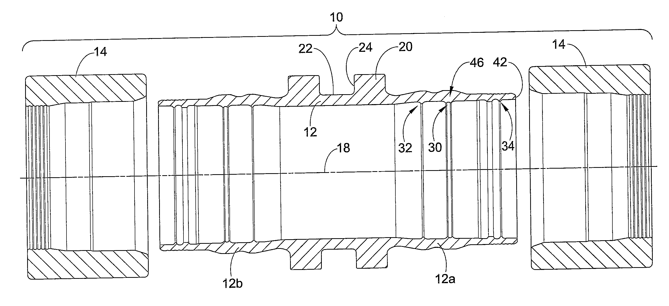
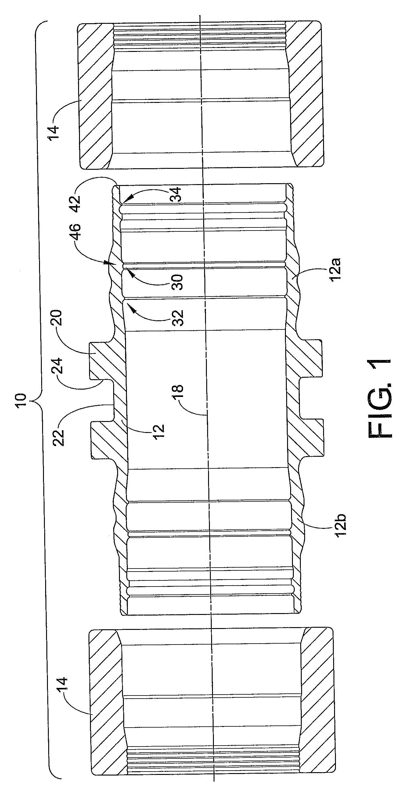
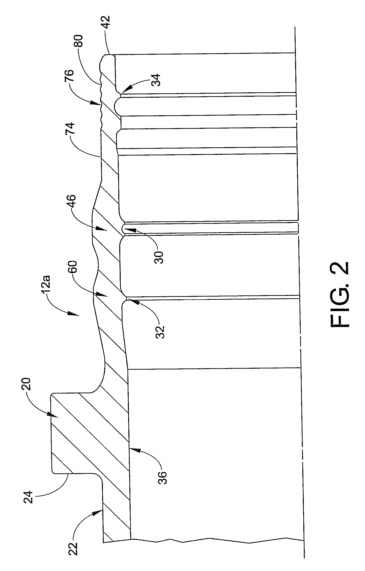
[0024]Referring now to the drawings, wherein like numerals refer to like parts throughout the several views, an improved fitting or fitting assembly 10 having complementary fitting materials is shown for coupling two sections of tube or pipe together and for providing a leak free seal connection with an associated fluid conduit during and after exposure to extreme heat. With spec...


PUM

PropertyMeasurementUnit
temperatureaaaaaaaaaa

Abstract

A fitting assembly for maintaining a leak free seal connection with an associated fluid conduit during and after exposure to extreme heat is provided. The fitting assembly includes a coupling body including an inside surface defining a bore for receiving the associated fluid conduit. The coupling body is made of a first corrosion resistant material having a first coefficient of thermal expansion. The at least one ring is made of a complementary second corrosion resistant material having a second larger coefficient of thermal expansion such that the second material will expand at a greater rate that the first material during heating to a first temperature generally exceeding annealing temperatures of both the first material and the second material. The second material contracts at a greater rate that the first material during subsequent cooling to a second temperature below the annealing temperatures thereby restoring compressive and tensile stresses in the associated fluid conduit and the fitting assembly for ensuring that the fitting assembly maintains a leak free seal connection with the associated fluid conduit.

Description

CROSS REFERENCE TO RELATED APPLICATIONS[0001]This application claims priority from U.S. Provisional Patent Application Ser. No. 60 / 725,582 filed Oct. 11, 2005, which is expressly incorporated herein by reference.BACKGROUND OF THE DISCLOSURE[0002]The present disclosure relates to fluid fittings, and more particularly, to an improved fitting employing complementary fitting materials which allow the fitting to maintain a tight leak seal during and post exposure to extreme heat. In one embodiment, a fitting includes a connector body having a sleeve that receives a tube or pipe therein and includes at least one radially extending seal for sealing and mechanically connecting to the tube or pipe when a swage ring is axially installed on the sleeve. The improved fitting will be described with particular reference to this embodiment, but it is to be appreciated that the improved fitting may relate to other similar environments and applications.[0003]Various types of fittings have been develo...

Claims


Application Information

Patent Timeline
Patent Type & Authority Patents(United States)
IPC IPC(8): F16L13/14
CPCF16L13/146F16L21/03F16L57/04
Inventor MCKAY, ALBERT A.
Owner LOKRING TECHNOLOGY
Learn More