Main gun shield for battle tank

a main gun and battle tank technology, applied in the field of military tanks, can solve the problems of extensive changes and expense of known methods of upgrading the m60 to a 120 mm gun

Active Publication Date: 2015-11-24
UNITED STATES OF AMERICA THE AS REPRESENTED BY THE SEC OF THE ARMY
View PDF31 Cites 10 Cited by
  • Summary
  • Abstract
  • Description
  • Claims
  • Application Information

AI Technical Summary

Benefits of technology

[0011]The shield may include a first tube inserted in the gunner's sight through bore and a second tube inserted in the small caliber weapon through bore.

Problems solved by technology

The known methods of upgrading the M60 to a 120 mm gun require extensive changes and expense.

Method used


Image

  • Main gun shield for battle tank
  • Main gun shield for battle tank
  • Main gun shield for battle tank

Examples


Embodiment Construction

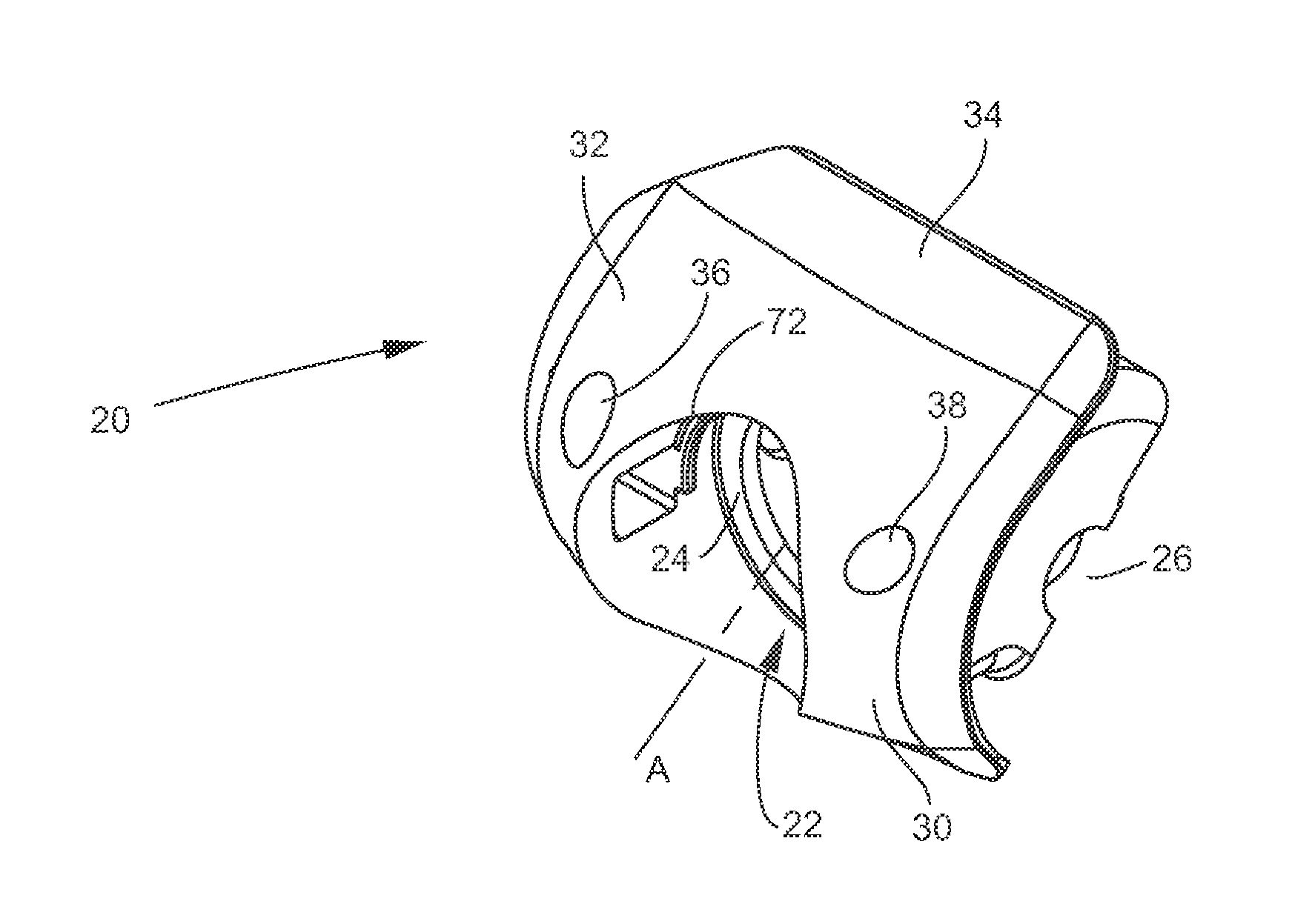
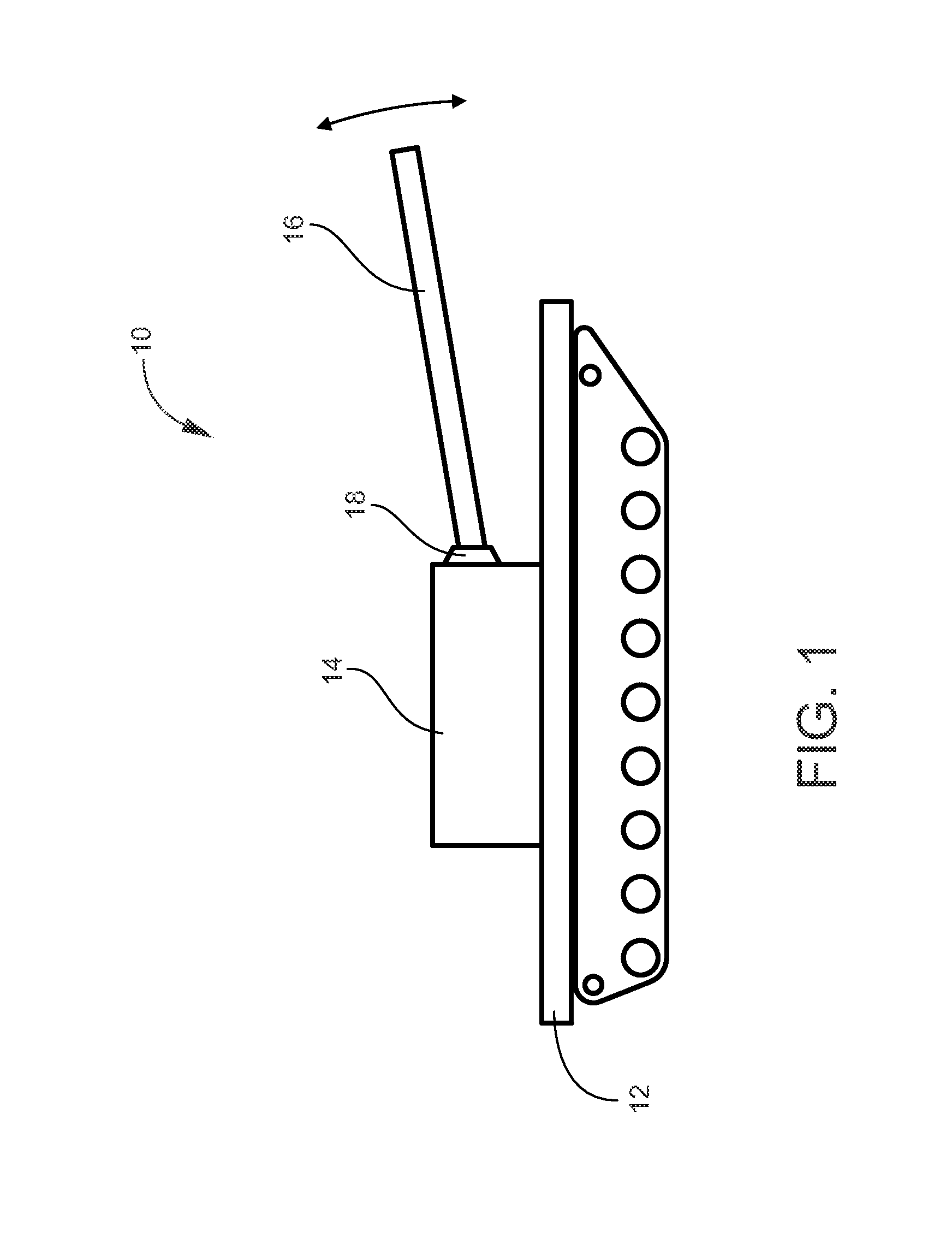
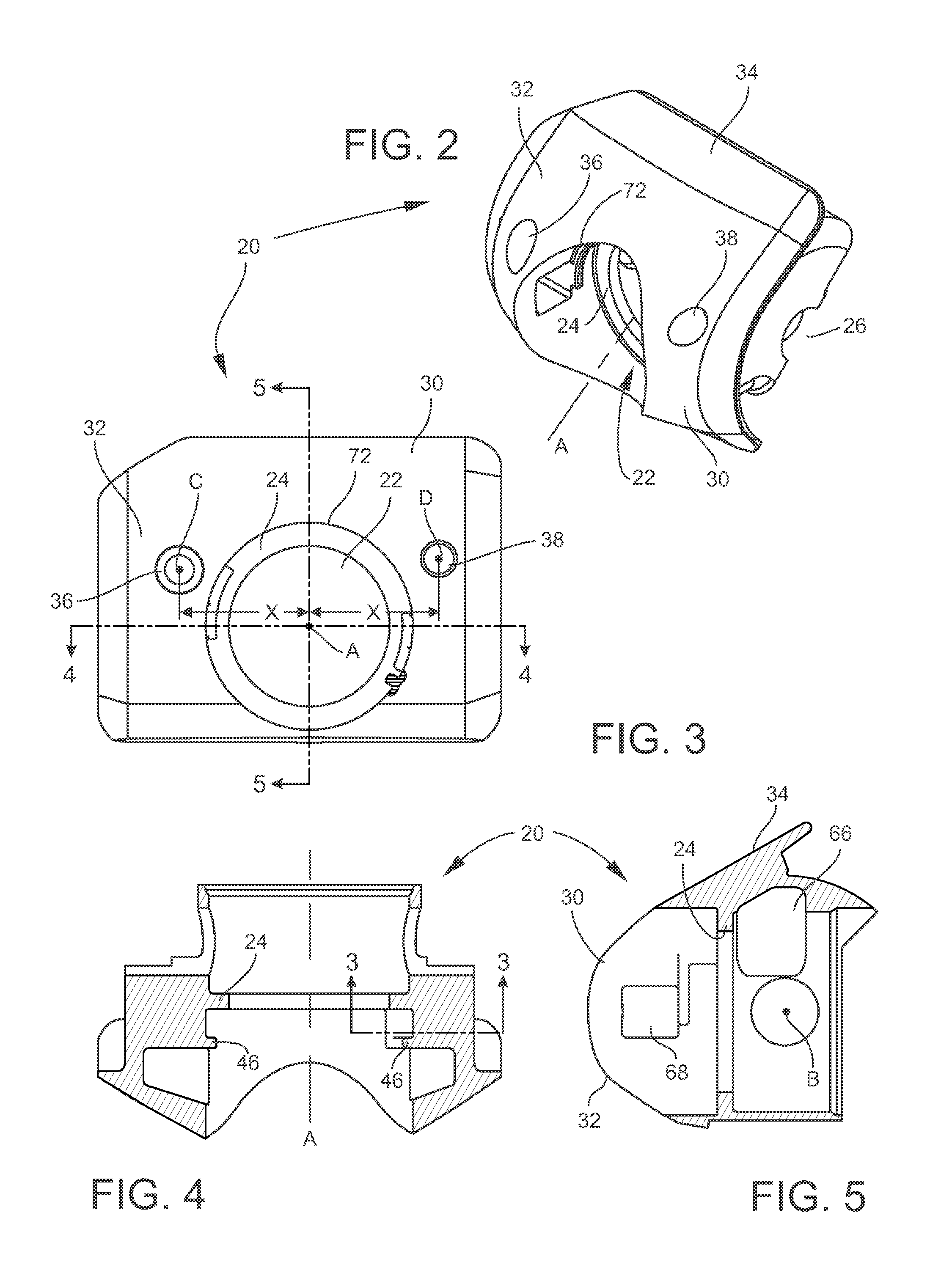
[0039]FIG. 1 is a schematic of a tank 10 having a hull 12 and a turret 14 rotatably fixed to hull 12. A main gun 16, such as a 120 mm gun, is rotatably fixed to turret 14. Turret 14 rotates horizontally about a vertical axis to vary the azimuth of gun 16. The elevation angle of gun 16 is varied by rotating the gun up and down with respect to turret 14, as shown by the arrows in FIG. 1. The interface 18 between the gun 16 and the turret 14 includes a means to mount the gun 16 to the turret 14 and to vary the elevation angle of the gun 16 with respect to the turret 14. The interface 18 is known as a rotor or shield. The term “shield” will be used herein to refer to the interface 18.

[0040]A novel shield for upgrading an M60 tank with a 120 mm gun uses the existing shield interfaces on the M60 tank. The novel shield includes a monolithic casting made of armor steel. The casting has features that may be formed by casting or by machining or a combination of both. A second, smaller casting...


PUM


Abstract

A shield for mounting a 120 mm gun to a tank turret includes a casting with a through hole configured to receive the 120 mm gun. A mounting flange is disposed in the through hole for fixing the 120 mm gun to the casting. A pair of trunnions are defined by a combination of the casting and a pair of respective trunnion caps. A shroud is removably fixed to the casting and includes a pair of bosses that interlock with a pair of protrusions in an interior of the casting.

Description

STATEMENT OF GOVERNMENT INTEREST[0001]The inventions described herein may be manufactured, used and licensed by or for the United States Government.BACKGROUND OF THE INVENTION[0002]The invention relates in general to military tanks and in particular to apparatus and methods for upgrading the main gun on a military tank.[0003]The U.S. M60 series main battle tank includes a 105 mm main gun with a rifled barrel. There is a desire to upgrade the main gun on the M60 to a 120 mm gun with a smooth bore barrel. The main gun upgrade improves the lethality of the M60 series tanks. The 120 mm gun, such as the M256 120 mm smooth bore gun, will not fit in the existing shield casting for the M68 105 mm gun.[0004]One method of upgrading the M60 to a 120 mm gun is to completely replace the turret with an M1A1 Abrams turret. This method involves a complete replacement of every component of the tank above the hull of the main battle tank. The new components include the M256 120 mm smooth bore gun, fi...

Claims


Application Information

Patent Timeline
Patent Type & Authority Patents(United States)
IPC IPC(8): F41H5/20F41A27/08F41A23/24
CPCF41H5/20F41A27/08F41A23/24F41H5/16F41A27/10
Inventor SMITH, LUCAS B.
Owner UNITED STATES OF AMERICA THE AS REPRESENTED BY THE SEC OF THE ARMY
Why Eureka
Try Eureka