Radiation detection panel, radiation imaging device, and diagnostic imaging device
a radiation detection panel and detection panel technology, applied in the field of radiation, can solve the problems of troublesome storage of data after imaging data and complicated process, and achieve the effect of accurate imaging data
- Summary
- Abstract
- Description
- Claims
- Application Information
AI Technical Summary
Benefits of technology
Problems solved by technology
Method used
Image
Examples
embodiment 1
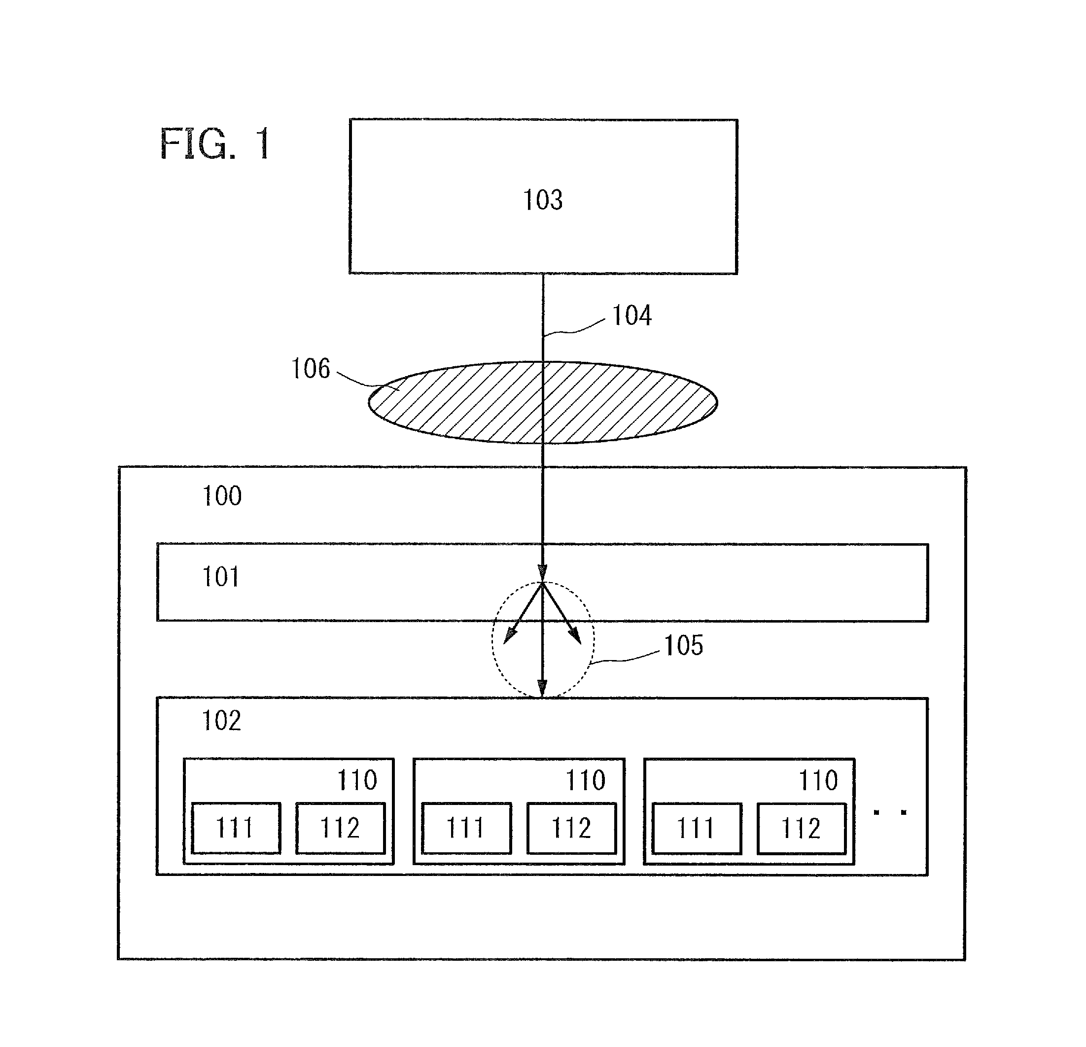
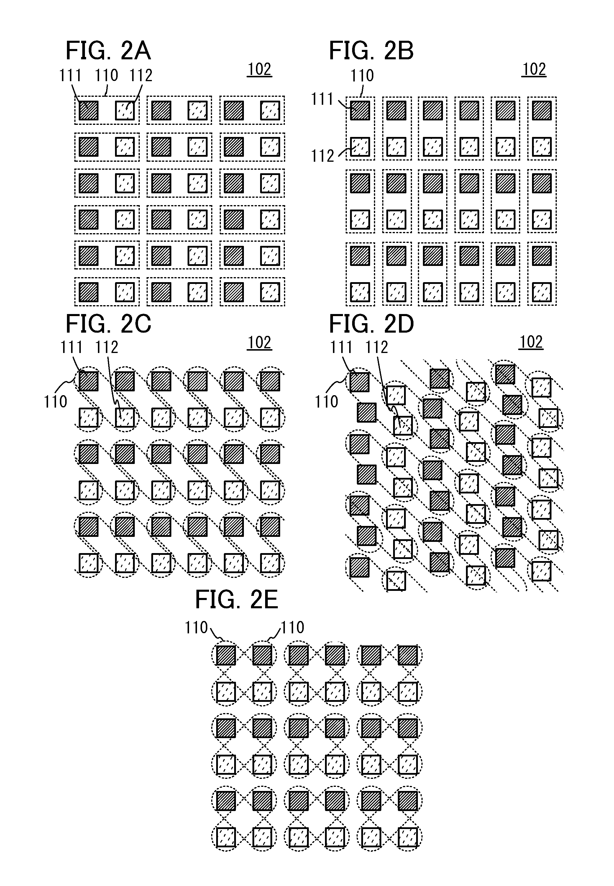
[0068]In Embodiment 1, the structure of a radiation detection panel will be described with reference to FIG. 1 and FIGS. 2A to 2E.
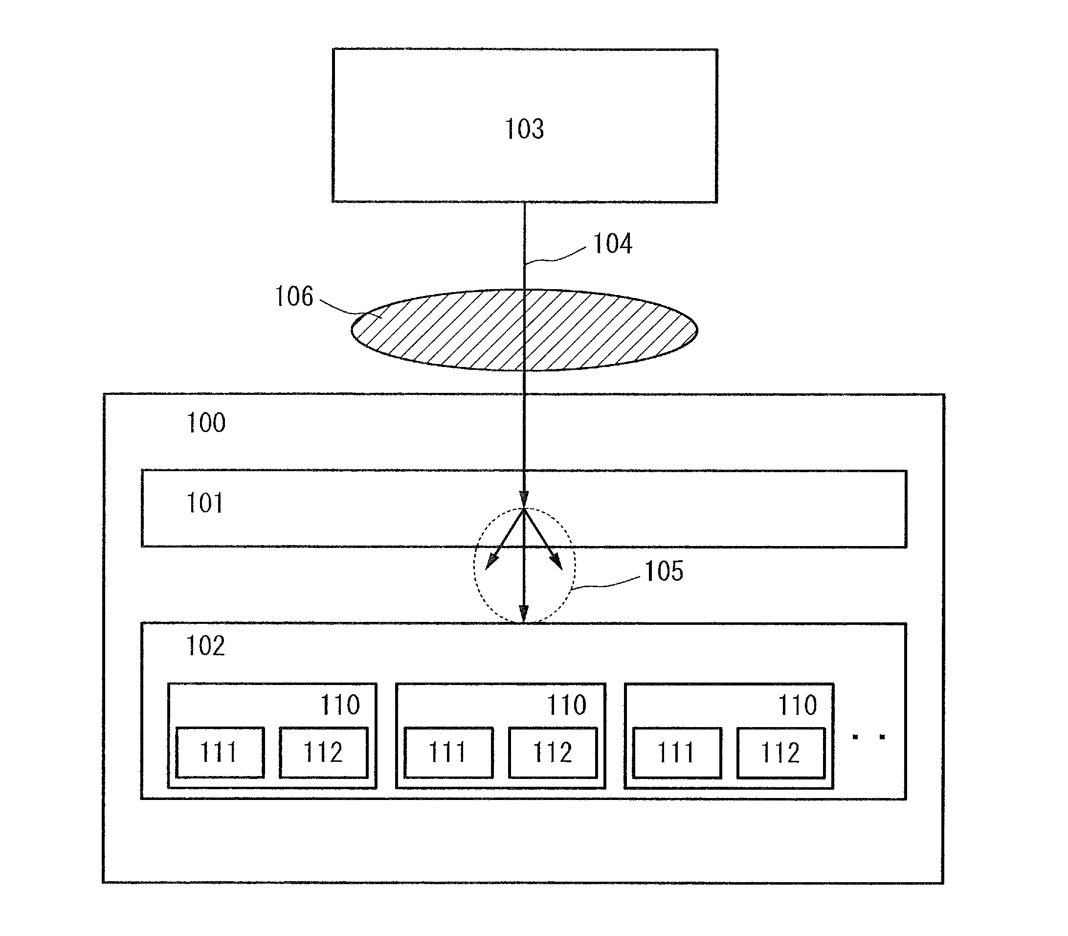
[0069]An overview of the structure of a radiation detection panel will be described with reference to FIG. 1. In FIG. 1, a radiation detection panel 100 includes a conversion unit 101 that receives radiation 104 emitted from the outside and converts the radiation 104 into light, and a plurality of detection circuits 110 each including a first output circuit 111 and a second output circuit 112 each of which outputs a signal based on light 105 emitted from the conversion unit 101. Note that the radiation 104 is emitted from a radiation source 103 and enters the radiation detection panel 100. An object 106 is disposed between the radiation detection panel 100 and the radiation source 103.
[0070]The conversion unit 101 includes a substance that absorbs energy of incident radiation (e.g., X-rays, γ-rays, β-rays, or neutron rays) and emits light (e.g., infrared ...
embodiment 2
[0145]Embodiment 2 shows examples of the structure of an integrator circuit used to be connected to the fourth wiring 314 (OUT).
[0146]FIG. 6A illustrates an integrator circuit including an operational amplifier circuit (also referred to as an op-amp). An inverting input terminal of the operational amplifier circuit is connected to the fourth wiring 314 (OUT) through a resistor R. A non-inverting input terminal of the operational amplifier circuit is grounded. An output terminal of the operational amplifier circuit is connected to the inverting input terminal of the operational amplifier circuit through a capacitor C.
[0147]Here, the operational amplifier circuit is assumed to be an ideal operational amplifier circuit. In other words, it is assumed that input impedance is infinite (the input terminals draw no current). Since the potential of the non-inverting input terminal and the potential of the inverting input terminal are equal in a steady state, the potential of the inverting in...
embodiment 3
[0157]In Embodiment 3, the configuration and operation flow of the detection circuit 110 including the first output circuit 111 and the second output circuit 112, which are different from those in Embodiment 1, will be described with reference to FIGS. 7A and 7B, FIG. 8, FIGS. 9A and 9B, and FIG. 10.
1)>
[0158]The detection circuit 110 including the first output circuit 111 and the second output circuit 112 may have a configuration illustrated in FIG. 7A. Although the components of the detection circuit in FIG. 7A are the same as those in FIG. 3A, the configuration in FIG. 7A differs from that in FIG. 3A in that one electrode of the photoelectric conversion element 300 is electrically connected to one of the source and the drain of the third transistor 303 and the other electrode of the photoelectric conversion element 300 is electrically connected to the first wiring 311 (PR).
[0159]Note that as described in Embodiment 1, it is possible to employ any of the following structures: a cap...
PUM
 Abstract
Description
Claims
Application Information
 - R&D
- Intellectual Property
- Life Sciences
- Materials
- Tech Scout
- Unparalleled Data Quality
- Higher Quality Content
- 60% Fewer Hallucinations
Browse by: Latest US Patents, China's latest patents, Technical Efficacy Thesaurus, Application Domain, Technology Topic, Popular Technical Reports.
© 2025 PatSnap. All rights reserved.Legal|Privacy policy|Modern Slavery Act Transparency Statement|Sitemap|About US| Contact US: help@patsnap.com


