Lock structure and guidance mechanism thereof

a technology of locking structure and guidance mechanism, which is applied in the direction of wing knobs, building locks, latching locks, etc., can solve problems such as the destruction of the lock structur

Active Publication Date: 2016-01-05
TAIWAN FU HSING INDAL
View PDF41 Cites 3 Cited by
  • Summary
  • Abstract
  • Description
  • Claims
  • Application Information

AI Technical Summary

Benefits of technology

[0004]The primary object of the present invention is to provide a lock structure, wherein a guidance mechanism of the lock structure includes an opening and a guidance track. A driving plank enables to be installed at the lock structure via the guidance track, which prevents the driving plank from wrong installation to avoid a destruction of the lock structure or reinstallation.
[0005]A lock structure in the present invention at least includes a driving plank and a guidance mechanism, wherein the driving plank is rotatable between an unlatch position and a lock position, and the guidance mechanism is rotatable between the unlatch position and the lock position as well. The guidance mechanism includes an opening and a guidance track, the driving plank is inserted into the opening of the guidance mechanism to make the guidance mechanism and the driving plank mutually coupled at the same unlatch position or mutually coupled at the same lock position through the guidance of the guidance track, which prevents the driving plank from wrong installation to avoid a destruction of the lock structure or reinstallation.

Problems solved by technology

Besides, a wrong installation for the driving plank 11 results in destruction of the lock structure 10 or reinstallation.

Method used


Image

  • Lock structure and guidance mechanism thereof
  • Lock structure and guidance mechanism thereof
  • Lock structure and guidance mechanism thereof

Examples


Embodiment Construction

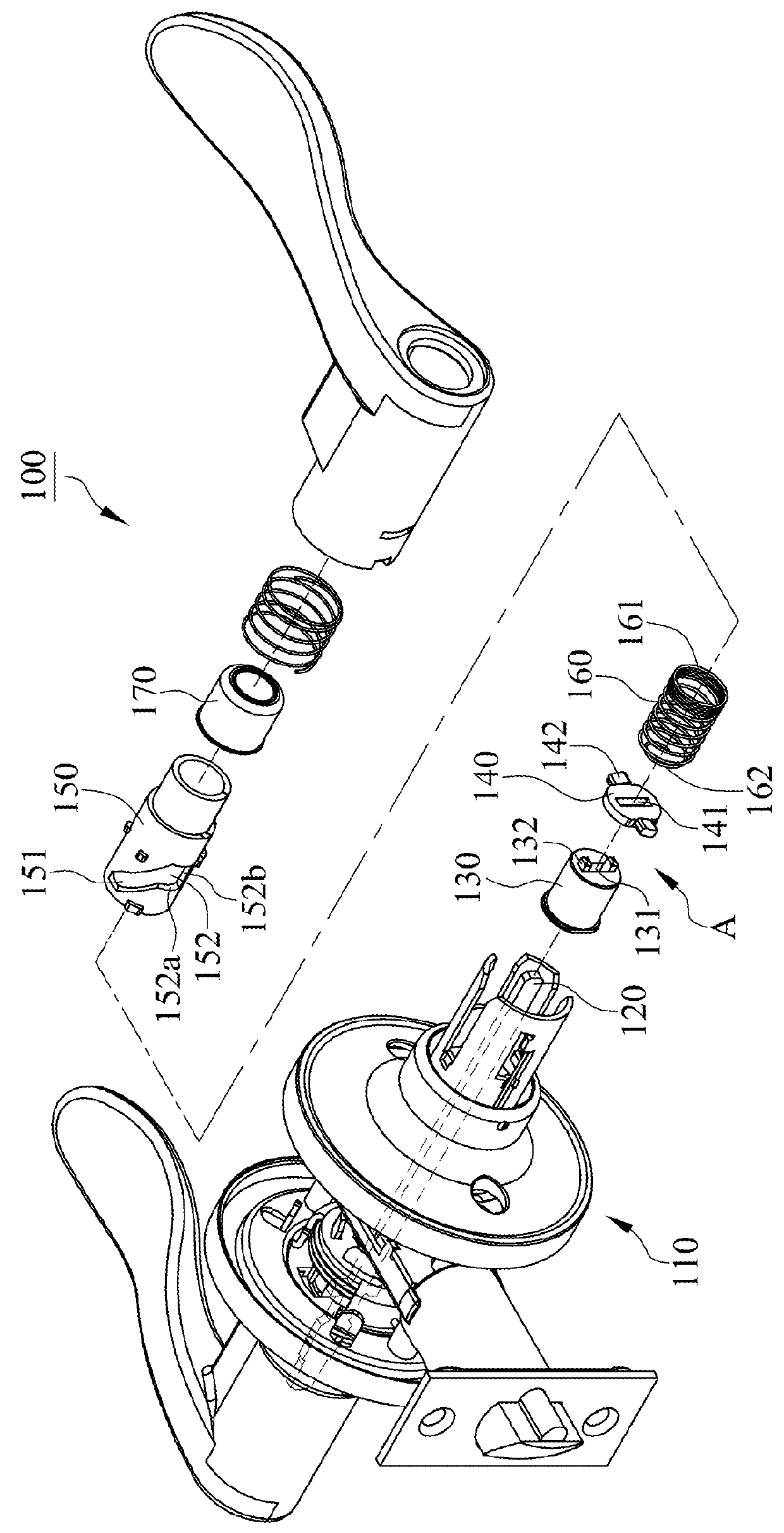
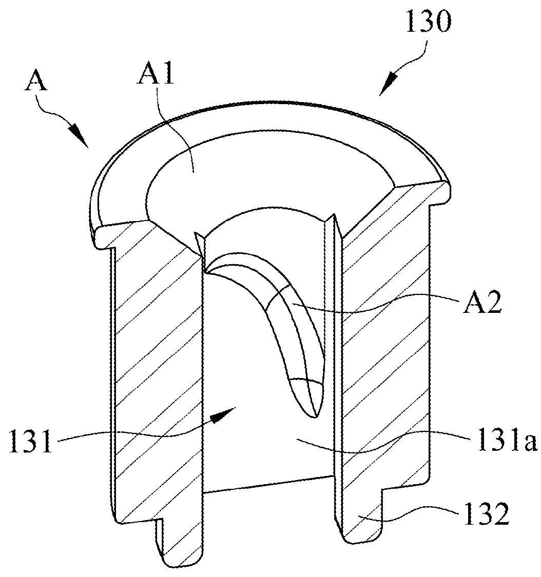
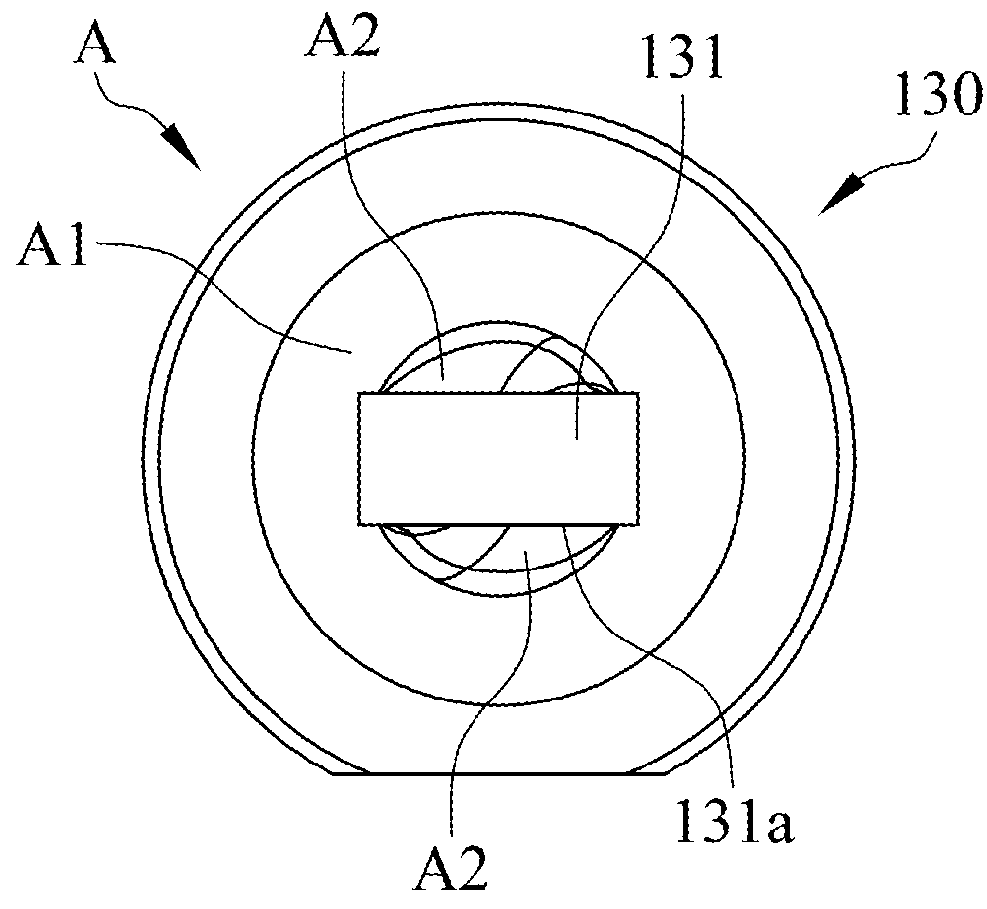
[0028]With reference to FIG. 1, a lock structure 100 in accordance with a first embodiment of the present invention includes a latch module 110, a driving plank 120, an actuation member 170, and a guidance mechanism A, wherein one end of the driving plank 120 couples to an outside lever where a key is inserted to unlock, and another end of the driving plank 120 couples to the guidance mechanism A which is coupled to an inside lever. The latch module 110 may be driven to unlatch a door by rotation of the inside lever or the outside lever. Despite the lock structure 100 installed at the inside lever and the outside lever in this embodiment, the lock structure 100 may also be installed at an inside knob and an outside knob based on actual demand. The driving plank 120 couples to the latch module 110 and is rotatable between an unlatch position and a lock position so that the lock structure 100 can be switched into a locked state or an unlocked state. The guidance mechanism A and the dr...


PUM


Abstract

A lock structure at least includes a driving plank and a guidance mechanism. The guidance mechanism and the driving plank are mutually coupled at a same unlatch position via the guidance mechanism, or, the guidance mechanism and the driving plank are mutually coupled at a same lock position, which prevents the driving plank from wrong installation to avoid a destruction of the lock structure or reinstallation.

Description

FIELD OF THE INVENTION[0001]The present invention is generally related to a lock structure, which particularly relates to the lock structure that makes a driving plank correctly installed via a guidance track of a guidance mechanism.BACKGROUND OF THE INVENTION[0002]With reference to FIG. 22, a conventional lock structure 10 includes a driving plank 11, an unlatch plate 12, an elastic member 13 and a controlled barrel 14, wherein the unlatch plate 12 and the elastic member 13 are disposed within the controlled barrel 14. The unlatch plate 12 comprises a transmission hole 12a and cooperates with an unlatch button coupled to an inside lever. In manufacturing process of the lock structure 10, manufacturer must ensure that the driving plank 11 and the transmission hole 12a of the unlatch plate 12 are aligned in a same installation direction so as to make the driving plank 11 directly inserted into the transmission hole 12a. Eventually, the lock structure 10 can be wrapped in and approves...

Claims


Application Information

Patent Timeline
Patent Type & Authority Patents(United States)
IPC IPC(8): E05B1/00E05B65/00E05B55/00E05B55/04E05B17/00
CPCE05B65/00E05B55/005E05B2017/0095Y10T70/5155
Inventor HUANG, CHAO-MING
Owner TAIWAN FU HSING INDAL
Why Eureka
Try Eureka