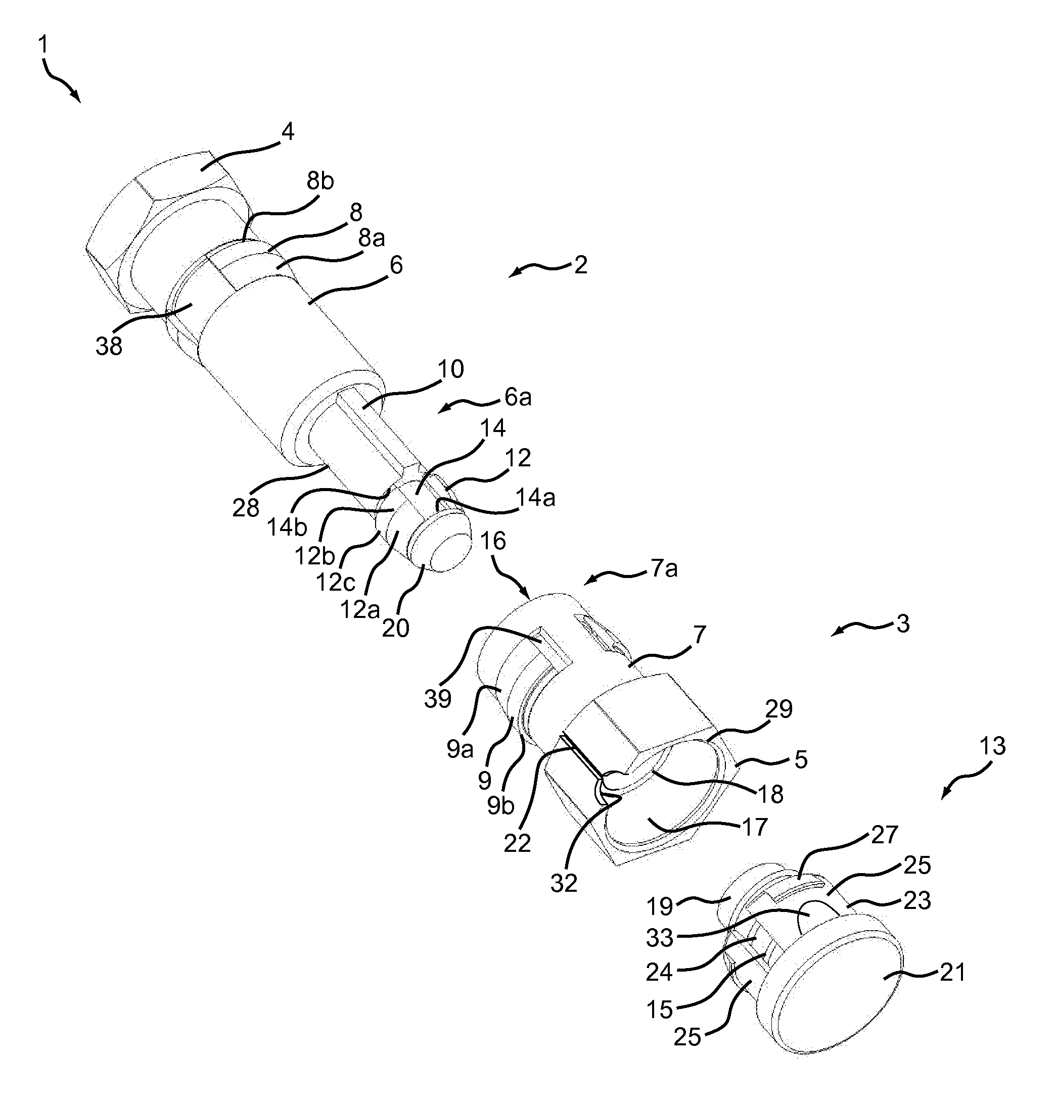
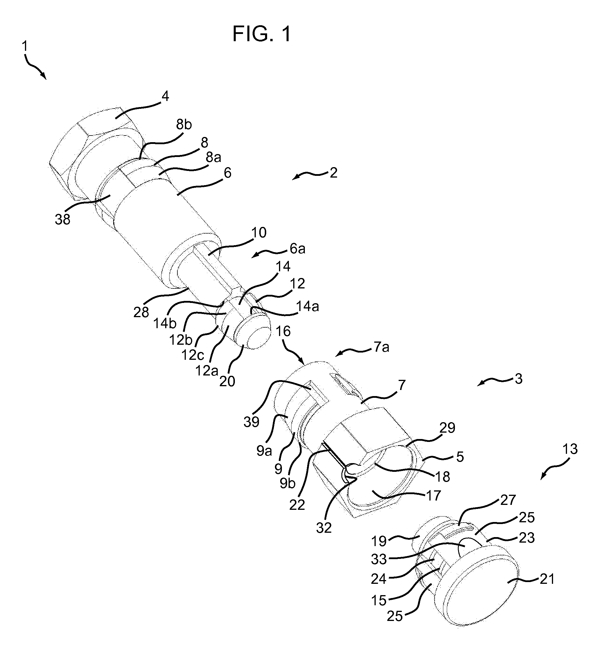
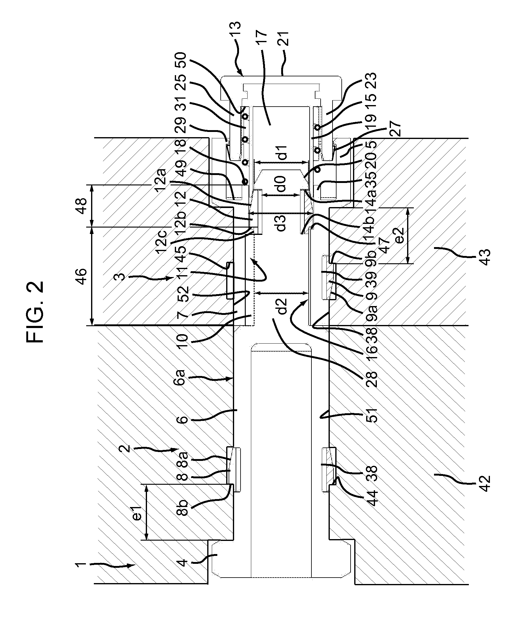
[0013]The invention proposes a fixing device with elongated mating members serving also as polarizers, which can be assembled very rapidly and intuitively, and which can be assembled and disassembled without using tools.
[0015]In other words, the actuator is adapted to move axially between a first position in which, when the two elongated mating members are inserted into one another, the interaction between the actuator and the elastic member allows axial locking of the two elongated mating members by the elastic member and a second position in which, when the two elongated mating members are inserted into one another, the interaction between the actuator and the elastic member brings about radial retraction of the elastic member so as to unlock the second elongated mating member axially relative to the first elongated mating member. In an advantageous embodiment, the elastic member may be assembled to the one of the elongated mating member, and the actuator may be assembled to the other elongated mating member. In a preferred embodiment, when the second elongated mating member is inserted into the first elongated mating member, the actuator is so configured that pushing the actuator in the direction of the assembled elongated mating members displaces the actuator from the first locking position to the second unlocking position. This makes the unlocking easy even with oily or slippery hands, for the actuator may be moved by a plunger inserted in the elongated mating member.
[0017]Preferably, the elastic member is assembled to one of the elongated mating members, and said elongated mating member comprises a polarizing shape allowing only one relative angular position of insertion of the second elongated mating member into the first elongated mating member, said polarizing shape being axially comprised between the elastic member and the head of the elongated mating member. In some embodiment, the elastic member can act as polarizing shape. In other embodiments, the polarizing shape is one piece with the elongated mating member, and is placed axially behind the elastic member. In this way, the polarizing shape cannot hinder the action of the actuator facing the elastic member.
[0026]In accordance with this embodiment, the plunger axially traverses at least a portion of the expansion portion and the actuator has an outside diameter substantially equal to the diameter of the expansion portion. The axial movement of the plunger can therefore be guided by a portion of the actuator bearing radially on the expansion portion of the first elongated mating member. The actuator is configured so that it can move axially relative to the expansion portion. In accordance with a different embodiment, the plunger may be pushed in until it axially traverses the whole of the expansion portion. In the pushed in position, the plunger therefore reduces the inside diameter for radial bearing engagement available inside the whole of the extension portion. In accordance with other embodiments, the actuator is mobile relative to the expansion portion but cannot be pushed in so that it passes through the whole of the expansion portion. Here “outside diameter of the actuator” means the diameter of the smallest circle inside which may be inscribed the portion of the actuator acting on the elastic member, i.e. the outside diameter of the tube when the actuator is a tube. In accordance with another alternative embodiment in which the actuator includes a group of axial pins, the outside diameter of the actuator could be the diameter of a circle circumscribing the pins. The expansion portion and the guide portion are preferably linked by a radial shoulder surface configured to retain the elastic member when the latter is expanded inside the first elongated mating member. In accordance with a different embodiment, the actuator may include an end the outside diameter of which is less than the diameter of the expansion portion, for example a portion with a diameter less than or equal to the inside diameter of the guide portion, so that the actuator is able not only to traverse the expansion portion but also to be inserted into a portion of the guide portion. In accordance with this embodiment, the plunger may axially traverse the expansion portion and at least an axial portion of the guide portion. In accordance with other, simpler embodiments, the actuator has an outside diameter enabling it to be guided by the expansion portion without enabling it to penetrate into the guide portion.
[0031]According to an advantageous embodiment, the free end of the first elongated mating member comprises a radial retaining rim protruding radially toward the inside of the head so as to limit locally the opening section of a cylindrical housing in which the plunger is inserted. The cylindrical housing may a delimited by a circular cylindrical section, or may be delimited by any generation section, such as a square or a hexagonal section. The radial retaining rim may be a continuous rim, or may comprise one or more separate protruding bulges which globally reduce the available maximum section allowed for the insertion of the plunger.
[0036]In accordance with one advantageous embodiment, the plunger has a shape adapted to be inserted in a counterpart shape provided on the head of the elongated mating member when the plunger is in a first angular position relative to the elongated mating member, the shape being adapted to prevent the plunger from being pushed into the elongated mating member in at least one second angular position of the plunger.


