Check patentability & draft patents in minutes with Patsnap Eureka AI!

Buffering device

a buffering device and buffering technology, applied in the direction of shock absorbers, vibration dampers, gas based dampers, etc., can solve the problems of resilient members which easily become invalid

Inactive Publication Date: 2016-02-09
HONG FU JIN PRECISION IND WUHAN CO LTD +1
View PDF3 Cites 0 Cited by
  • Summary
  • Abstract
  • Description
  • Claims
  • Application Information

AI Technical Summary

Benefits of technology

The device effectively slows down the door closing speed of vending machines without influencing the door opening speed, providing consistent performance by minimizing mechanical fatigue through the use of air pressure resistance.

Problems solved by technology

However, the buffering device includes resilient members which easily become invalid because of mechanical fatigue.

Method used


Image

  • Buffering device
  • Buffering device
  • Buffering device

Examples


Embodiment Construction

[0011]The disclosure is illustrated by way of example and not by way of limitation. In the figures of the accompanying drawings in which like references indicate similar elements. It should be noted that references to “an” or “one” embodiment in this disclosure are not necessarily to the same embodiment, and such references mean “at least one.”

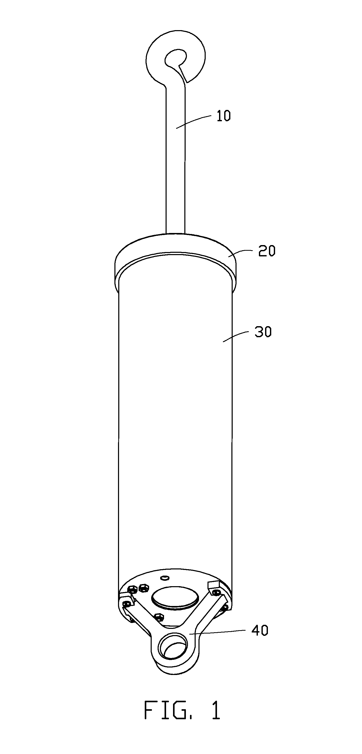
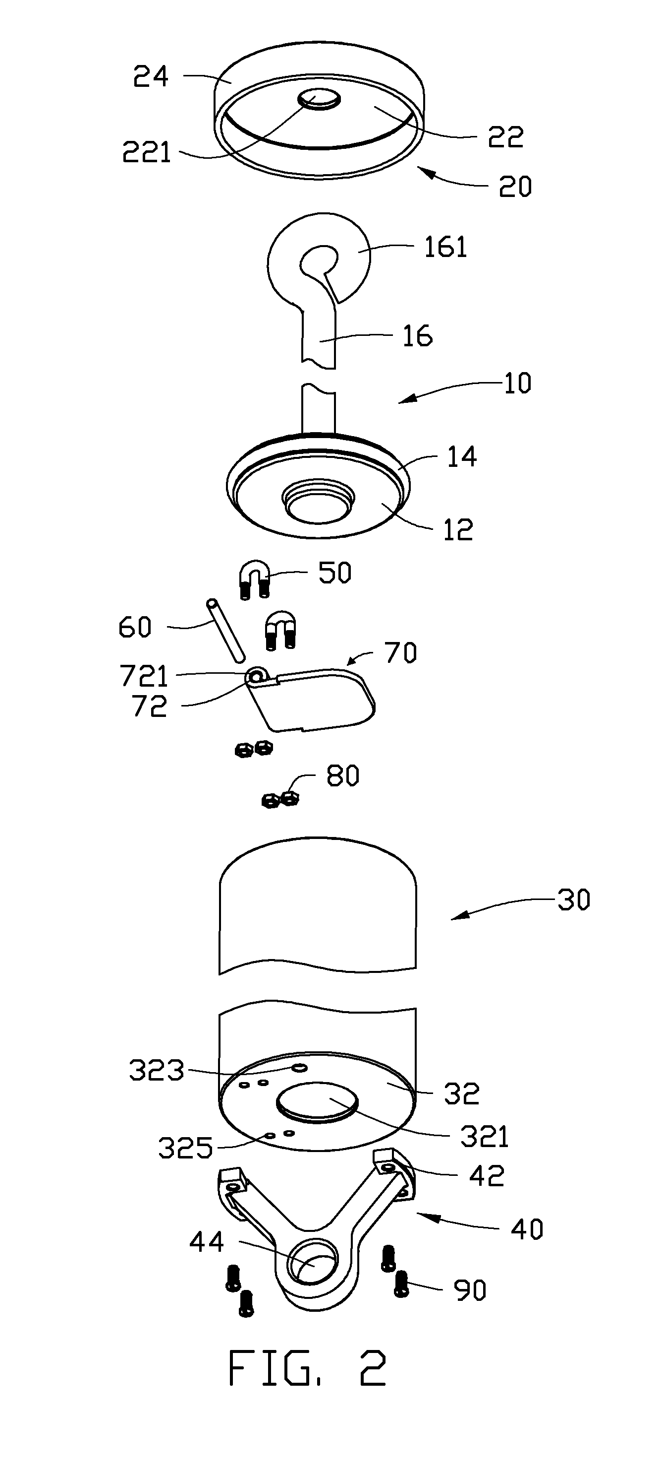
[0012]FIGS. 1 and 2 show an embodiment of a buffering device, which includes a piston module 10, a cover 20, a cylindrical casing 30, a mounting member 40, a pair of latching members 50, a pivot post 60, a shielding piece 70, two pairs of screw caps 80, and two pairs of fasteners 90.

[0013]The piston module 10 includes a valve 12, a piston ring 14 surrounding the valve 12, and a piston rod 16. The valve 12 is attached to a lower end of the piston rod 16. A curved mounting portion 161 extends from an upper end of the piston rod 16.

[0014]The cover 20 includes a circular plate 22 and a ring-shaped flange 24 extending substantially perpendicularly ...


PUM


Abstract

A buffering device includes a cylindrical casing and a piston module movably mounted in the cylindrical casing. The cylindrical casing includes a base plate and a shielding piece pivotally attached to the base plate. An air inlet and an air outlet are defined in the base plate. A diameter of the air inlet is greater than that of the air outlet. When the piston module is moving towards the base plate, the shielding piece is rotated to a closed position to shield the air inlet by air pressure above the shielding piece. When the piston module is moving away from the base plate, the shielding piece is rotated to an open position to expose the air inlet by environmental air pressure.

Description

BACKGROUND[0001]1. Technical Field[0002]The present disclosure relates to a buffering device.[0003]2. Description of Related Art[0004]A vending machine includes a cabinet and a door pivotably attached to the cabinet. A buffering device is attached to the door. When the door is rotating to a closed position, the buffering device provides resistance to slow down a rotation speed of the door. However, the buffering device includes resilient members which easily become invalid because of mechanical fatigue.[0005]Therefore, there is room for improvement within the art.BRIEF DESCRIPTION OF THE DRAWINGS[0006]Many aspects of the embodiments can be better understood with reference to the following drawings. The components in the drawings are not necessarily drawn to scale, the emphasis instead being placed upon clearly illustrating the principles of the embodiments. Moreover, in the drawings, like reference numerals designate corresponding parts throughout the several views.[0007]FIG. 1 is a...

Claims


Application Information

Patent Timeline
Patent Type & Authority Patents(United States)
IPC IPC(8): F16F9/516F16F9/02
CPCF16F9/516F16F9/0218
Inventor FAN, YONG-CHANG
Owner HONG FU JIN PRECISION IND WUHAN CO LTD
Features
  • R&D
  • Intellectual Property
  • Life Sciences
  • Materials
  • Tech Scout
  • Unparalleled Data Quality
  • Higher Quality Content
  • 60% Fewer Hallucinations
Learn More