
Free-space optical mesh network

a free-space optical and mesh network technology, applied in the field of free-space optical communication systems, can solve the problems of poor resilience, low throughput, and high latency of low-connectivity systems

Active Publication Date: 2016-02-23
RAYTHEON CO
View PDF15 Cites 33 Cited by
  • Summary
  • Abstract
  • Description
  • Claims
  • Application Information

AI Technical Summary

Benefits of technology

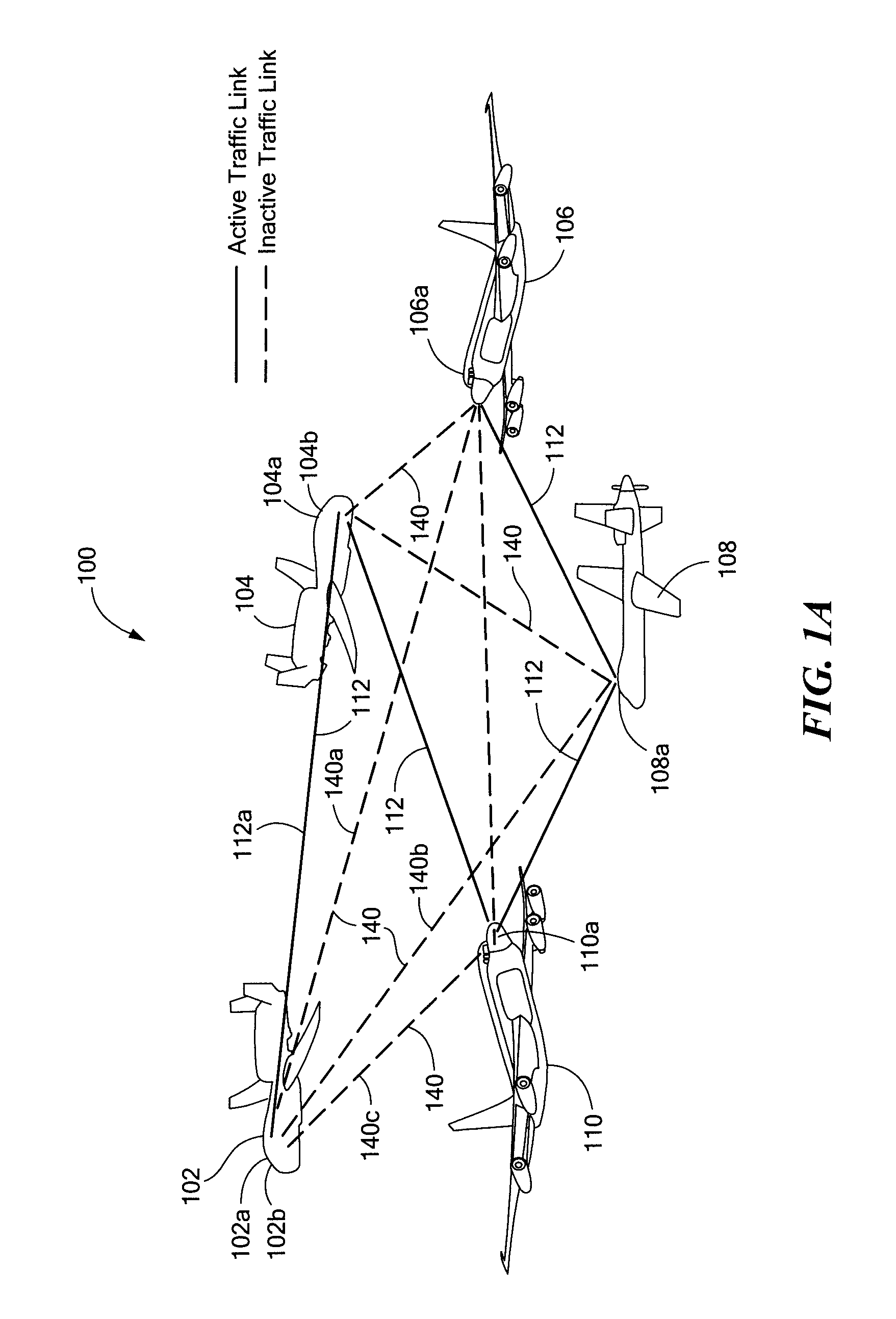
[0007]According to another aspect, a method for transmitting data in a free-space optical network includes pointing an optical data beam from a first node to a second node during a first period of time, transmitting data from the first node to the second node during the first period of time, pointing the optical data beam from the first node to a third node during a second period of time, and transmitting data from the first node to the third node during the second period of time.

Problems solved by technology

Such low-connectivity systems may have high latency, low throughput, and poor resilience as any single broken optical link may partition the network into disconnected segments.
However, this approach does not scale in practice, as each increase in node degree requires an additional high-speed optical communications terminal and thus significantly increases the cost and size, weight, and power (SWaP) characteristics.
However, such hybrid networks do not actually achieve a higher optical node degree and thus may suffer from degraded data rates, higher probability of detection, and lower jam resistance when a single optical traffic link is broken.

Method used


Image

  • Free-space optical mesh network
  • Free-space optical mesh network
  • Free-space optical mesh network

Examples


Embodiment Construction

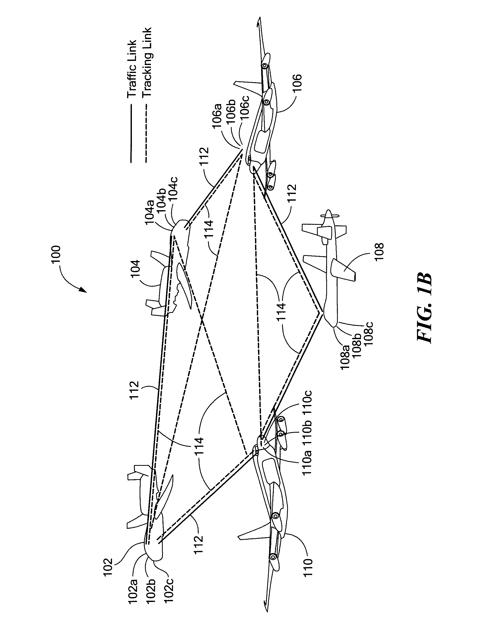
[0017]Before describing the present disclosure, some introductory concepts and terminology are explained. The term “node degree” is herein used to refer to the number of links terminating at a given node within a network. The term “meth network” is herein used to refer to any network with a high node degree, generally greater than 2. The term “optical terminal” refers to any apparatus or device capable of transmitting and / or receiving free-space optical beams. It will be appreciated that the optical terminals herein may further be capable of receiving data and / or tracking remote optical terminals. The terms “hop”, “hopping”, and “beam hopping” all generally refer to the process of repointing a transmitted free-pace optical beam from a first direction to a second direction and / or reconfiguring an optical terminal to receive such a beam. The term “traffic link” refers to any communications link capable of carrying user data at a high data rate and may be either unidirectional or, more...


PUM


Abstract

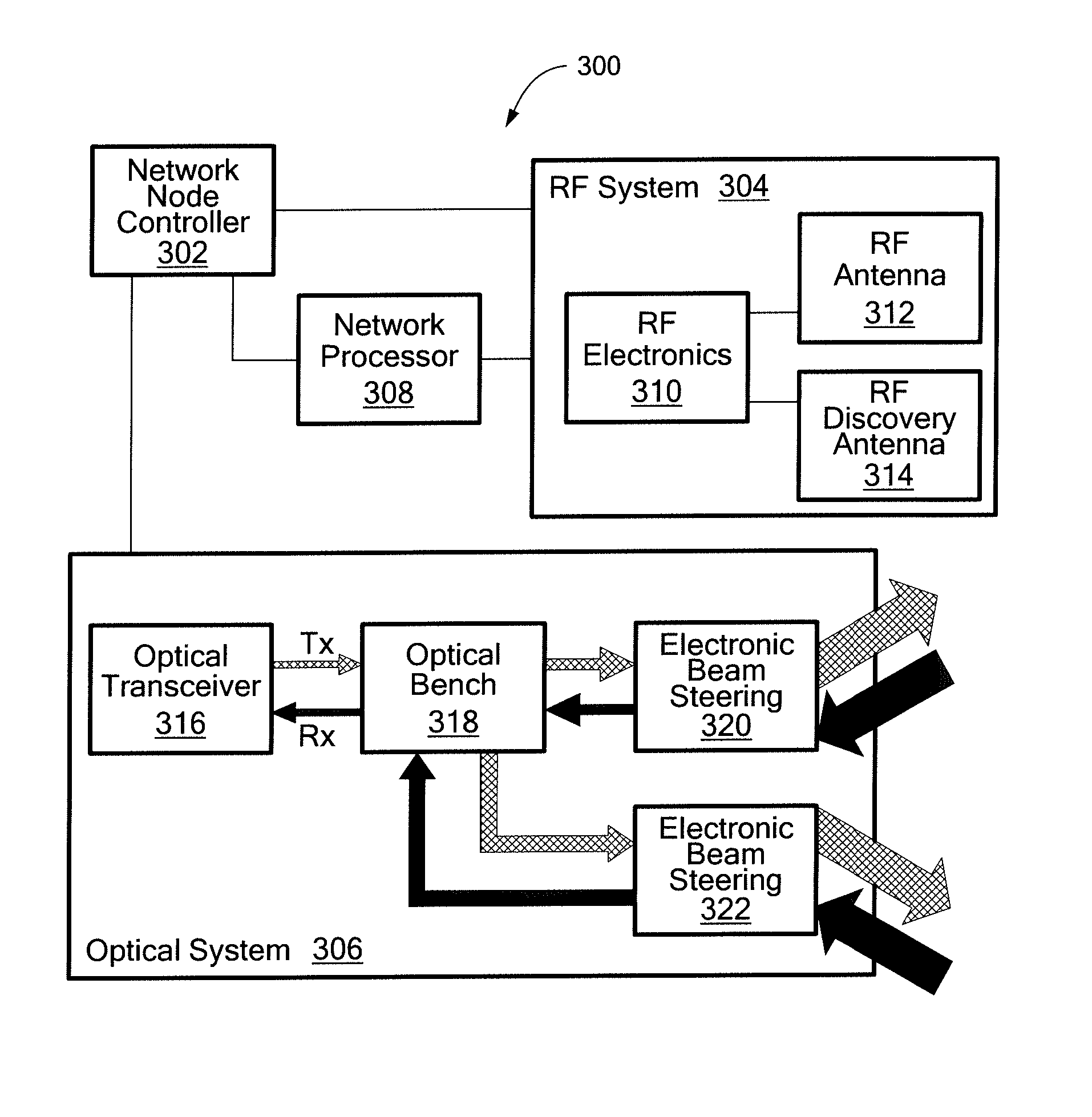
The disclosure provides a practical system and methods for implementing an adaptive free-space optical network with a high-connectivity, dynamic mesh topology. The network can have operational characteristics similar to those of RF mobile ad-hock networks. Each node has one or more optical terminals that may utilize space-time division multiplexing, which entails rapid spatial hopping of optical beams to provide a high dynamic node degree without incurring high cost or high size, weight, and power requirements. As a consequence the network rapidly sequences through a series of topologies, during each of which connected nodes communicate. Each optical terminal may include a plurality of dedicated acquisition and tracking apertures which can be used to increase the speed at which traffic links can be switched between nodes and change the network topology. An RF overlay network may be provided to act as a control plane and be used to provide node discovery and adaptive route planning for the optical network.

Description

CROSS REFERENCE TO RELATED APPLICATIONS[0001]This application claims the benefit and priority of U.S. Provisional Patent Application No. 61 / 839,045 filed on Jun. 25, 2013, which application is hereby incorporated by reference in its entirety.STATEMENT REGARDING FEDERALLY SPONSORED RESEARCH[0002]Not Applicable.FIELD OF THE INVENTION[0003]This invention relates generally to a free-space optical communication system and, more particularly, to a free space optical mesh network.BACKGROUND OF THE INVENTION[0004]Highly-connected radio frequency and microwave communication networks, commonly referred to as mesh networks, are known. Mesh networks provide high availability by maintaining a high degree of connectivity between nodes. Compared to RF communications, Free-Space Optical (FSO) communications provide higher data rates, lower probability of detection, and are less susceptible to jamming. In addition, FSO communications are not subject to spectrum usage limits. While RE mesh networks a...

Claims


Application Information

Patent Timeline
Patent Type & Authority Patents(United States)
IPC IPC(8): H04B10/112H04B10/114H04B10/00
CPCH04B10/1129H04B10/1141H04B10/1143H04B10/1149H04B10/22H04B7/18504H04B10/11
Inventor MINISCALCO, WILLIAM, J.
Owner RAYTHEON CO
Learn More