
Method and device for channel-adapted signal transmission in optical networks

a channel-adapted signal and optical network technology, applied in electromagnetic transmitters, electrical equipment, electromagnetic transmission, etc., can solve the problems of inability to determine, substantial increase in the cost of systems of this type, and inability to actually use them

Active Publication Date: 2012-05-22
DEUTSCHE TELEKOM AG
View PDF11 Cites 4 Cited by
  • Summary
  • Abstract
  • Description
  • Claims
  • Application Information

AI Technical Summary

Benefits of technology

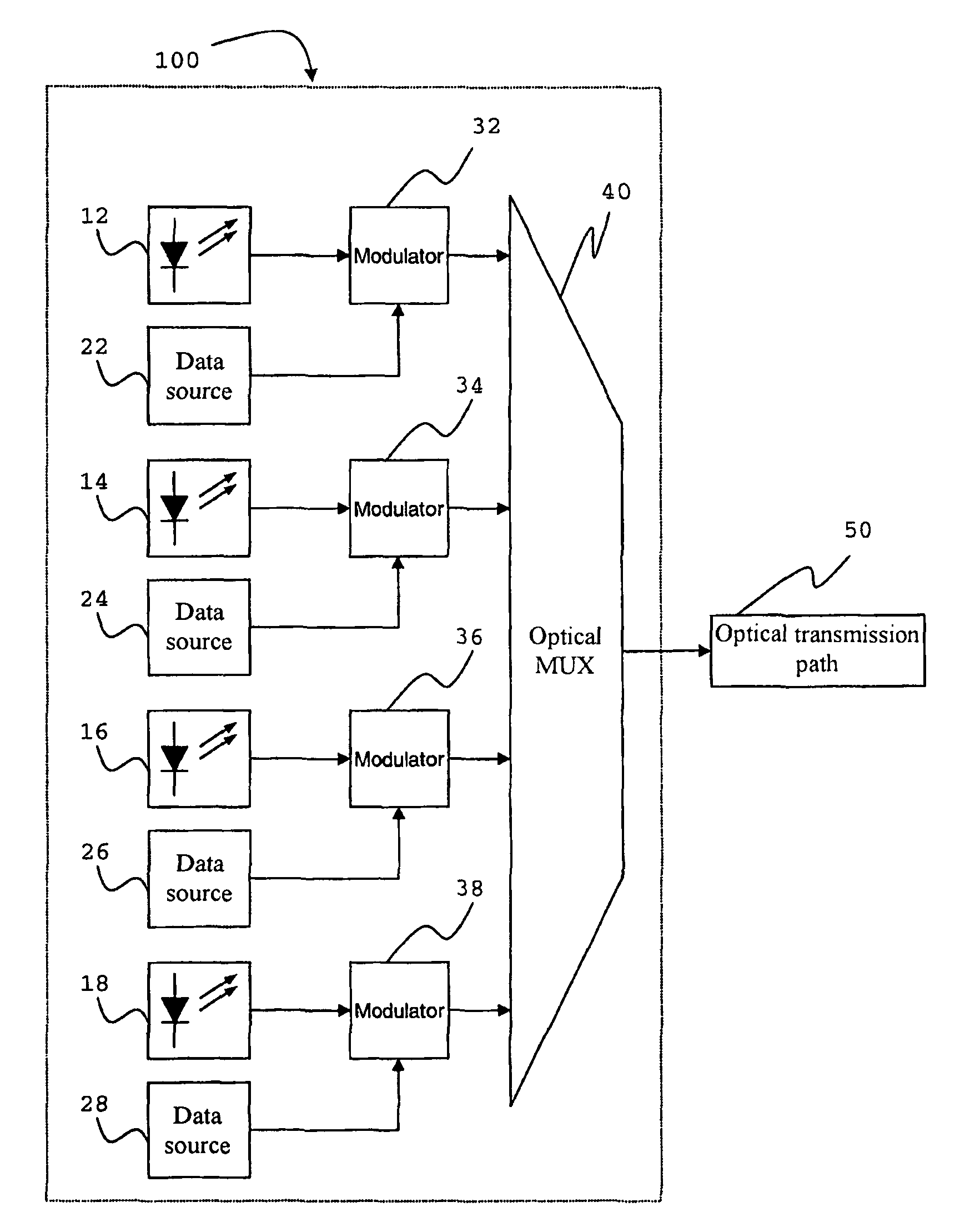
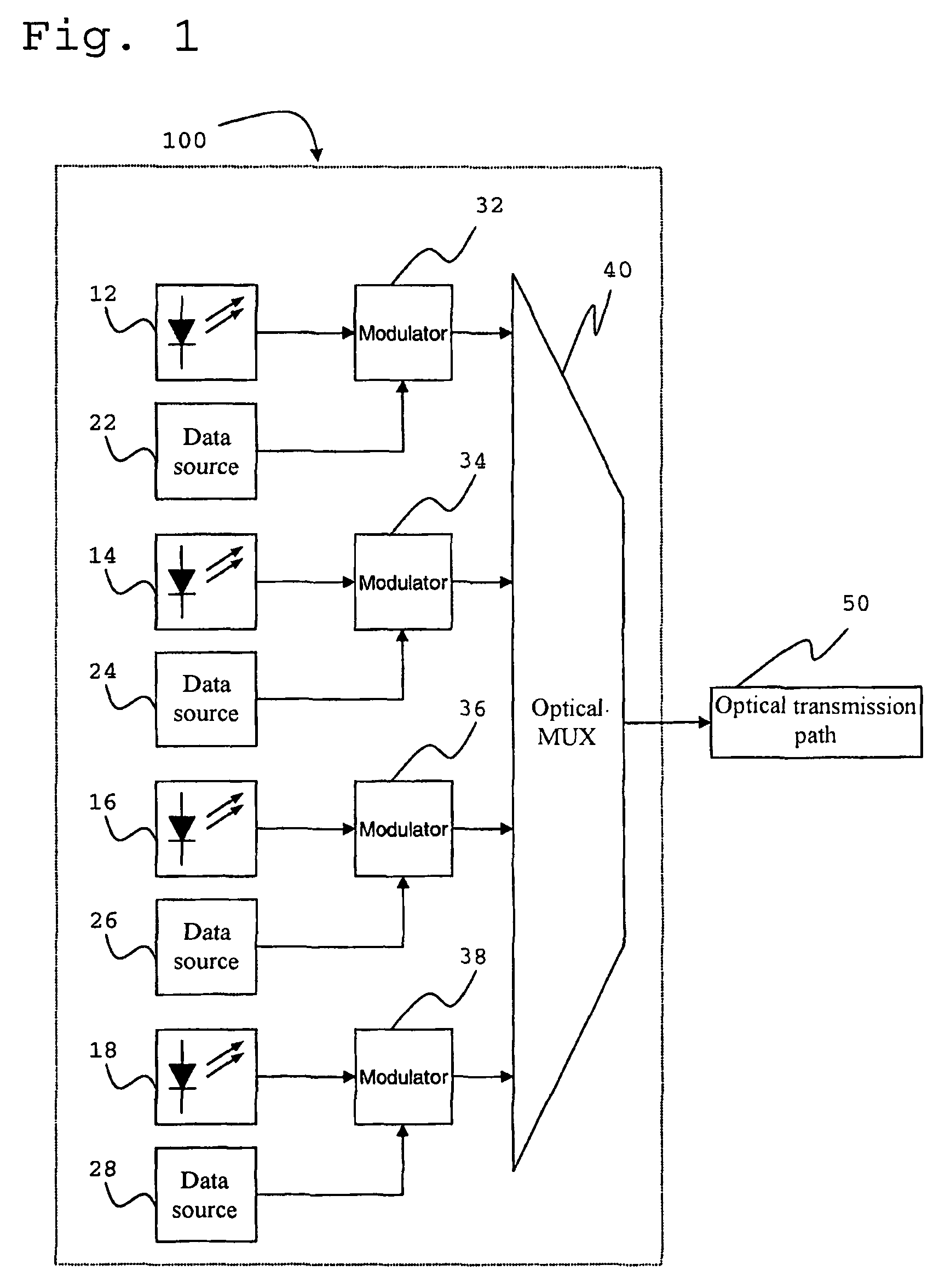
[0007]In another embodiment, the present invention provides a wavelength multiplexing system for optical data transmission having at least two transmission channels of different wavelengths. The system includes: a controllable transmitter configured to provide an optical signal, wherein the controllable transmitter is connected via an optical transmission path to a controllable receiver configu

Problems solved by technology

Other parameters vary stochastically and thus cannot be determined by calculations beforehand.
Both the requirement for fast reaction times and that for wide adjustment ranges lead to a substantial increase of costs in systems of this type.
Thus, for example, appropriate PMD compensators are indeed technically feasible for the physical effect of polarization mode dispersion, but the actual use thereof is prevented by the lack of cost efficiency.

Method used


Image

  • Method and device for channel-adapted signal transmission in optical networks
  • Method and device for channel-adapted signal transmission in optical networks
  • Method and device for channel-adapted signal transmission in optical networks

Examples


Embodiment Construction

[0016]By way of overview and introduction, an embodiment of the invention provides a way of increasing the transmission quality of a wavelength multiplexing system, in particular without adaptive compensation of stochastic variations of physical parameters of the optical transmission path. Moreover, an embodiment of the present invention provides an increase in the efficiency of the bandwidth utilisation of a wavelength multiplexing system.

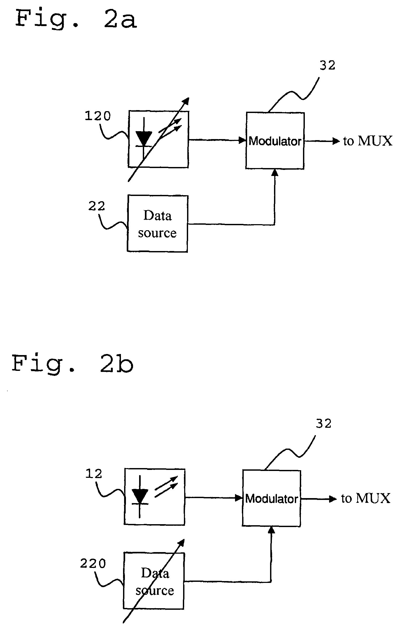
[0017]Accordingly, a method embodying the invention for optical data transmission in a wavelength multiplexing system involves determining at least one value which is a measure of a physical property of the optical transmission path of the wave multiplexing system and automatically adjusting at least one transmission parameter of at least one transmission channel of the wavelength multiplexing system as a function of the determined value, the wavelength multiplexing system having at least two transmission channels of different wavelengths.

[0018]Ad...


PUM


Abstract

A method for optical data transmission in a wavelength multiplexing system having at least two transmission channels of different wavelengths includes determining at least one value which is a measure of a physical property of an optical data transmission path of the wavelength multiplexing system; and automatically adjusting a transmission parameter of at least one of the transmission channels as a function of the determined at least one value.

Description

CROSS REFERENCE TO RELATED APPLICATIONS[0001]This is a U.S. national phase application under 35 U.S.C. §371 of International Patent Application No. PCT / DE2006 / 002179, filed Dec. 8, 2006, and claims benefit of German Patent Application No. 10 2005 060 256.8, filed Dec. 16, 2005. The International Application was published in German on Jul. 12, 2007 as WO 2007 / 076767 A1 under PCT Article 21(2).FIELD[0002]The invention relates generally to optical data transmission systems and in particular to a wavelength multiplexing system and a method for optical data transmission in a system of this type.BACKGROUND[0003]In contemporary optical transmission networks, data is transmitted via optical channels with channel data rates of up to 40 Gbit / s. In order to increase the transmission capacity, not only one but a plurality of channels are transmitted on one glass fibre in the wavelength multiplex. From DE 699 04 805 T2, for example, there is known a wavelength multiplexing system which allows th...

Claims


Application Information

Patent Timeline
IPC IPC(8): H04J14/02H04B10/12H04B10/04H04B10/077H04B10/079
CPCH04B10/077H04B10/07953H04B10/07955H04J14/02H04J14/0221
Inventor VORBECK, SASCHALEPPLA, RALPHSCHNEIDERS, MALTEGUNKEL, MATTHIASWEIERSHAUSEN, WERNER
Owner DEUTSCHE TELEKOM AG
Learn More