
Optical network logical topology reconstruction method, reconstruction controller and optical network system

A technology of optical network and controller, which is applied in the field of computer network, can solve problems such as difficult to meet various communication characteristics efficiently, and achieve the effect of system resource utilization and power consumption

Active Publication Date: 2017-12-22
XFUSION DIGITAL TECH CO LTD
View PDF3 Cites 5 Cited by
  • Summary
  • Abstract
  • Description
  • Claims
  • Application Information

AI Technical Summary

Problems solved by technology

However, the fixed and single interconnection network structure of the existing data center is difficult to efficiently meet the needs of various communication features.

Method used


Image

  • Optical network logical topology reconstruction method, reconstruction controller and optical network system
  • Optical network logical topology reconstruction method, reconstruction controller and optical network system
  • Optical network logical topology reconstruction method, reconstruction controller and optical network system

Examples


Embodiment Construction

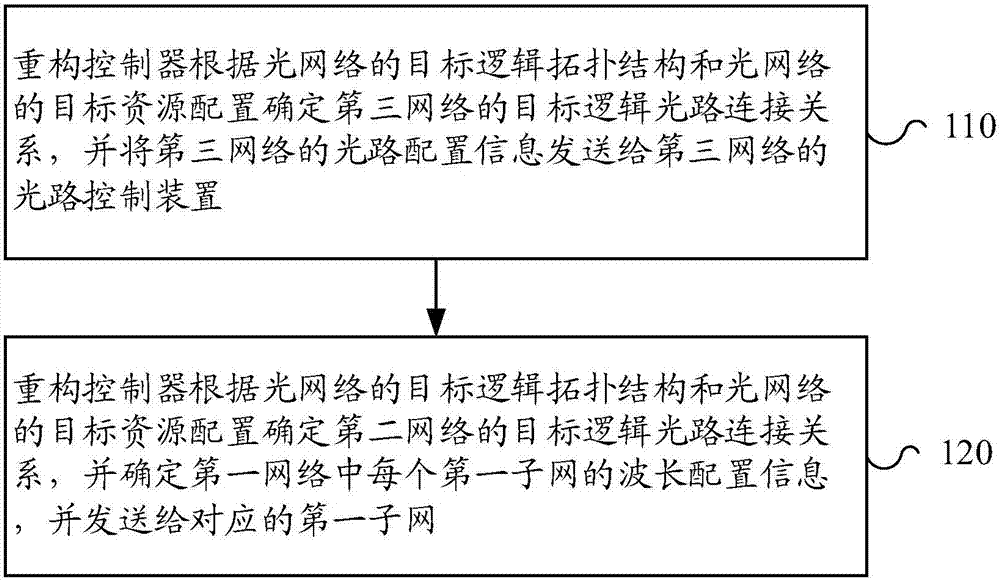
[0072] figure 1 It is a flow chart of the method for topology reconstruction of an optical network according to an embodiment of the present invention. It is applied to an optical network. The optical network includes the first layer network (Layer1, also called the first network), the second layer network (Layer2, also The second network), the third layer network (Layer3, also called the third network) and the reconfiguration controller. Among them, the first layer network is connected to the second layer network, the second layer network is connected to the third layer network, and the reconfiguration controller is connected to the first and third layers. It should be noted that the layers of the network in this embodiment are abstract and generalizations of some devices, and do not represent a specific device. In specific implementation, each layer includes some devices. If there are two layers of networks connected, it means that the devices on the two layers are connected...


PUM


Abstract

The embodiment of the invention provides an optical network logical topology reconstruction method. The optical network comprises a first network, a second network, a third network and a reconstruction controller, wherein the first network comprises a plurality of first sub-networks, the second network is an optical interconnection network based on optical wavelength exchange and comprises a plurality of sub-networks, the third network is an optical interconnection network based on space exchange, and the reconstruction controller determines a target logical optical path connection relation of the third network according to a target logical topology structure of the optical network and target resource configuration of the optical network, and sending the optical path configuration information of the third network to an optical path control device of the third network; the reconstruction controller determines a target logic optical path connection relation of the second network according to the target logical topology structure of the optical network and the target resource configuration of the optical network, determines wavelength configuration information of each first sub-network in the first network, and sends the information to the corresponding first sub-network.

Description

[0001] This application claims the priority of a Chinese patent application filed with the Chinese Patent Office on November 10, 2016, the application number is 201610988995.6, and the invention title is "Optical Network Logical Topology Reconstruction Method, Reconfiguration Controller and Optical Network System". The entire content is incorporated into this application by reference. Technical field [0002] The embodiments of the present invention relate to the field of computer networks, and more specifically, to a logical topology reconstruction method of an optical network, a reconstruction controller, and an optical network system. Background technique [0003] The rapid development of the Internet and cloud computing has caused exponential growth in data storage and interaction. This brings severe challenges to the interconnection network design of data centers, especially the diversity of applications makes how to efficiently use data center resources become a major proble...

Claims


Application Information

Patent Timeline
IPC IPC(8): H04Q11/00
CPCH04Q11/0005
Inventor 元国军曹政潘玮
Owner XFUSION DIGITAL TECH CO LTD
Learn More