Wing for an aircraft, aircraft and method for reducing aerodynamic drag and improving maximum lift

a technology of aerodynamic drag and wing, applied in the direction of drag reduction, airflow influencers, transportation and packaging, etc., can solve the problems of increasing the drag in flight scenarios, reducing the lift, and performing inferior in comparison to a dedicated design for a single flight phase. achieve the effect of reducing aerodynamic drag and improving maximum li

Active Publication Date: 2016-03-08
AIRBUS OPERATIONS GMBH
View PDF72 Cites 22 Cited by
  • Summary
  • Abstract
  • Description
  • Claims
  • Application Information

AI Technical Summary

Benefits of technology

[0005]An aspect of the invention proposes a wing having a wing tip extension, wherein the wing is adapted for improving the stall behavior of the wing tip extension essentially without aerodynamic penalties due to passive devices that extend from the surface of the wing.

Problems solved by technology

This means that the final wing end geometry is the best for the complete envelope, while potentially performing inferior in comparison to a dedicated design for a single flight phase.
This can lead to a decrease of lift and an increase of drag in flight scenarios, where the high lift devices are generally used.

Method used


Image

  • Wing for an aircraft, aircraft and method for reducing aerodynamic drag and improving maximum lift
  • Wing for an aircraft, aircraft and method for reducing aerodynamic drag and improving maximum lift
  • Wing for an aircraft, aircraft and method for reducing aerodynamic drag and improving maximum lift

Examples


Embodiment Construction

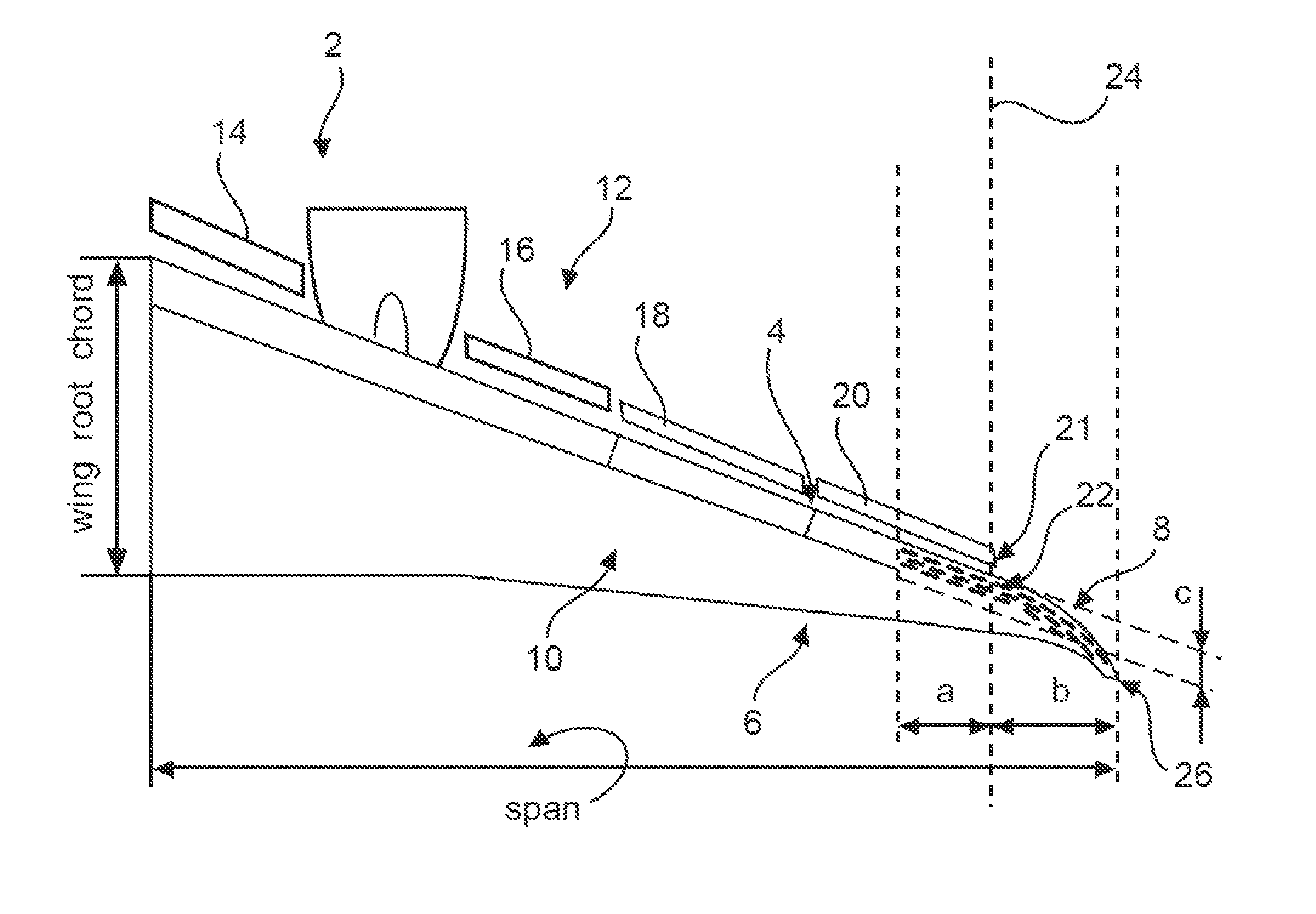
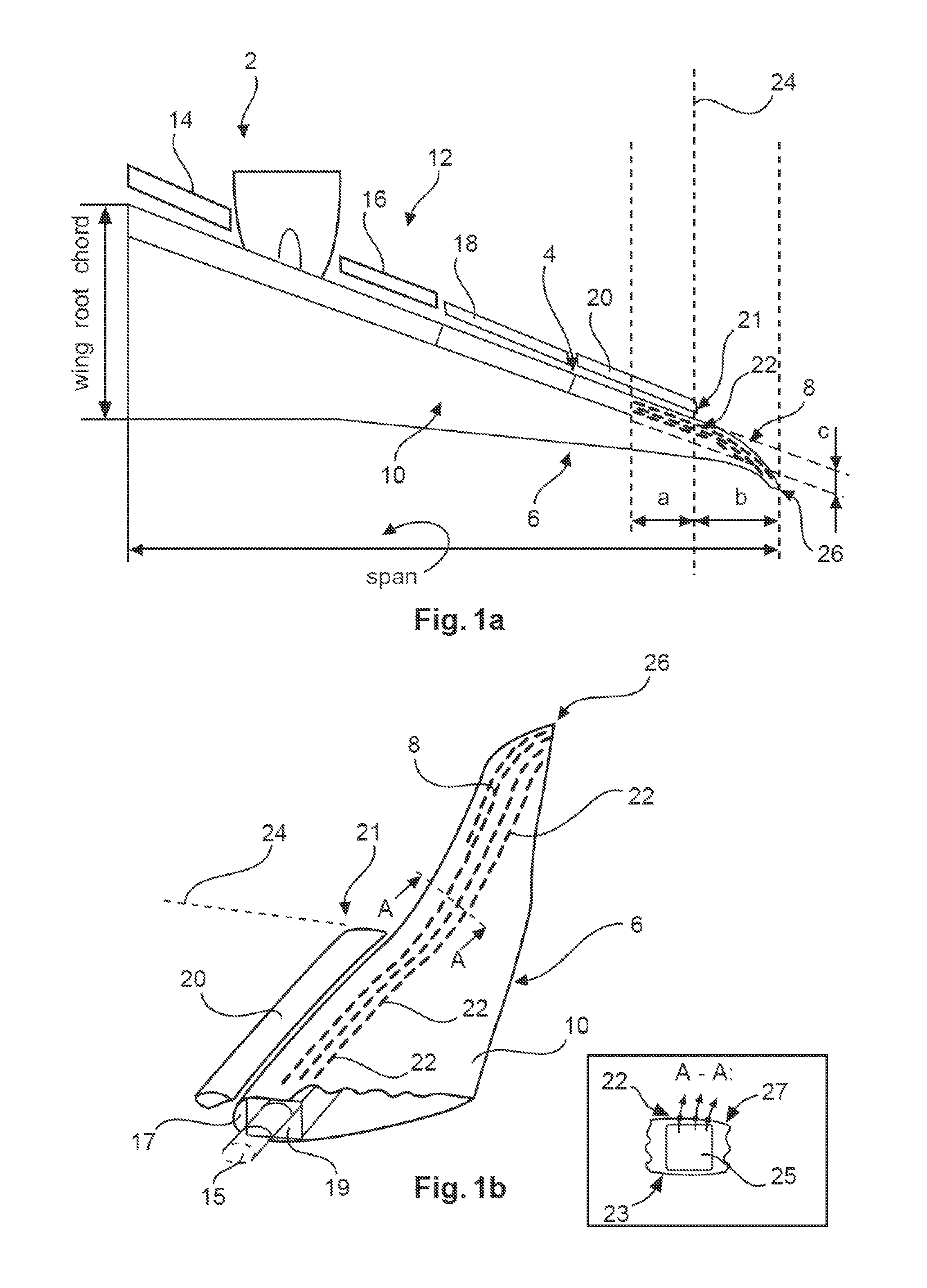
[0031]FIG. 1a shows a schematic view on a wing 2 according to an embodiment of the invention. The wing 2 comprises a leading edge 4, a trailing edge 6 and a wing tip extension 8. The wing tip extension 8 may comprise a shape with a more or less complex curvature and usually a dihedral angle at an end region. It is connected to or integrated in an outboard region of a main wing 10 which comprises a leading edge high lift device arrangement consisting of individual slats 14, 16, 18 and 20, wherein slat 20 is an outboard slat. The actual number of slats 14 to 20 per wing 2 is only chosen as an example and is not meant for limiting the scope of protection.

[0032]The outboard slat 20 is located adjacent to the wing tip extension 8, such that after deployment an end face 21 the outboard slat 20 is located in an upstream location influencing the flow around or impinging onto the wing tip extension 8. Furthermore, due to a clearly increased angle of attack of the wing 2 during takeoff or lan...


PUM


Abstract

A wing for an aircraft includes a leading edge and a wing tip extension extending from an end of a main wing region to a wing tip. The wing tip extension includes an arrangement of openings at least from the end of a main wing region to the wing tip along the leading edge, which openings are connected to an air conveying device for conveying air through the openings. Thereby in flight states with a low flight velocity the flow around a wing tip extension can be harmonized such that the drag is decreased and the lift of the wing is increased.

Description

CROSS-REFERENCE TO RELATED APPLICATIONS[0001]This application claims the benefit of the filing date of European Patent Application No. 12 162 156.9 filed Mar. 29, 2012 and of U.S. Provisional Patent Application No. 61 / 617,169 filed Mar. 29, 2012, the disclosure of which applications is hereby incorporated herein by reference.TECHNICAL FIELD[0002]The invention relates to a wing for an aircraft, an aircraft and a method for reducing aerodynamic drag and improving maximum lift.BACKGROUND OF THE INVENTION[0003]In commercial aircraft wing tip extensions are often installed for the purpose of improved efficiency due to a reduction of lift-induced drag and due to the increased lift generated at the wing tip. While wing tip extensions are usually designed for cruise flight conditions they may comprise an unwanted stall behavior during takeoff and landing. While the wing itself usually comprises high lift devices, e.g. in the form of slats arranged at the leading edge with the purpose of del...

Claims


Application Information

Patent Timeline
Patent Type & Authority Patents(United States)
IPC IPC(8): B64C23/06B64C21/02
CPCB64C23/065B64C21/02Y02T50/164Y02T50/166B64C23/069Y02T50/10
Inventor RECKZEH, DANIELGOELLING, BURKHARDLENGERS, MATTHIAS
Owner AIRBUS OPERATIONS GMBH
Why Eureka
Try Eureka