
Communication system and network relay device

a communication system and relay technology, applied in the field of communication system and network relay device, can solve the problems of ensuring redundancy and risk of reducing communication bandwidth, and achieve the effect of suppressing the reduction of communication bandwidth and improving fault toleran

Active Publication Date: 2016-03-29
APRESIA SYST LTD
View PDF5 Cites 0 Cited by
  • Summary
  • Abstract
  • Description
  • Claims
  • Application Information

AI Technical Summary

Benefits of technology

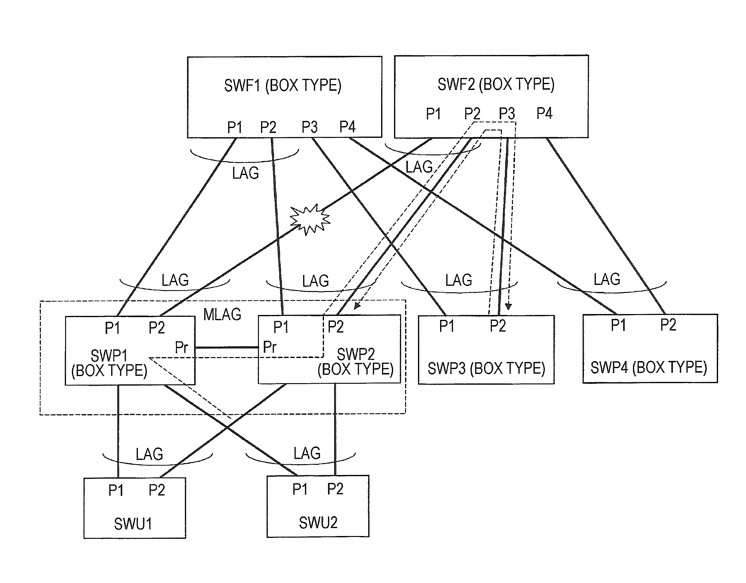
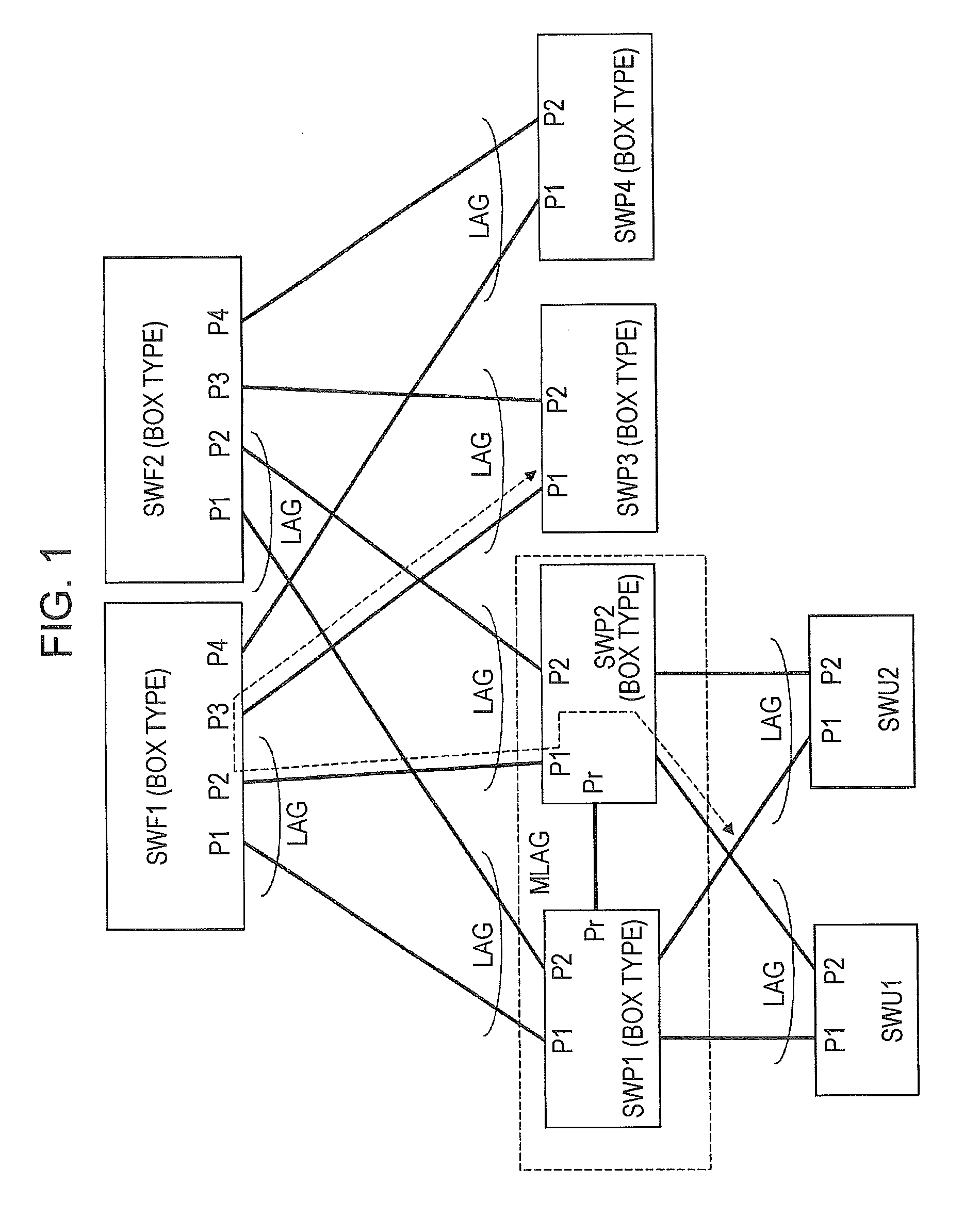
[0007]In this box type fabric system, one port switch, for example, is connected to a plurality of fabric switches through a plurality of communication lines so that link aggregation can be configured for a plurality of ports that become connection sources thereof. Load distribution and redundancy can be achieved within link aggregation when link aggregation is configured. When, for example, there is a demand to increase the communication bandwidth, the communication bandwidth can be easily increased with low costs by installing more fabric switches. Furthermore, in addition to increasing the aforementioned communication bandwidth in the system, the number of ports can also be easily increased with low costs by installing more port switches. As a result, a flexible system that addresses user requirements can be constructed at a low cost through the use of this system in comparison to a system made up of chassis-type switch devices.

Problems solved by technology

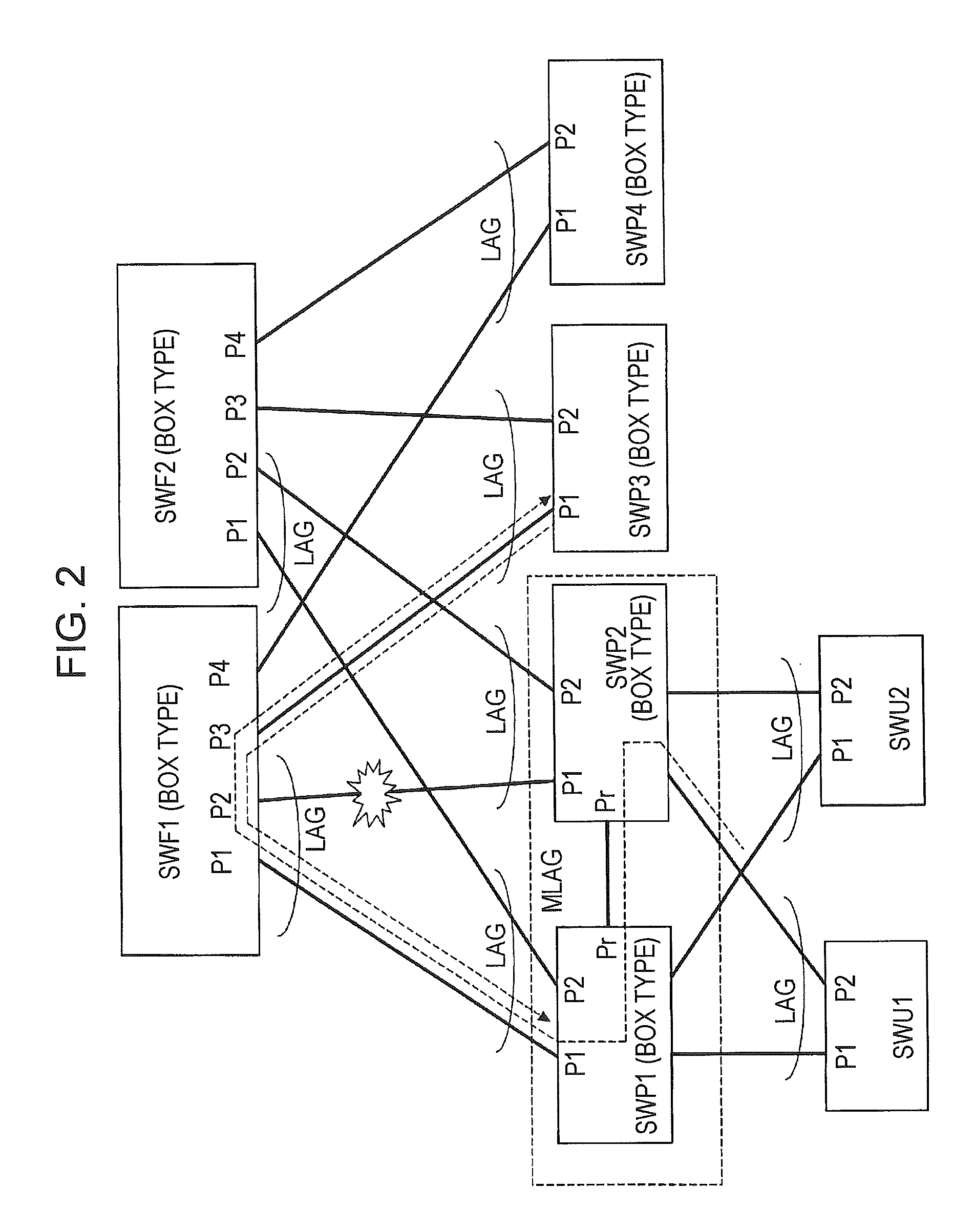
However, while redundancy can be assured through the aforementioned link aggregation function when, for example, a fault occurs in a communication line or a fabric switch in the box-type fabric system, there may be a problem in assuring redundancy when a fault occurs in a port switch.
As a result, it was found that there is a risk of a reduction in communication bandwidth due to the occurrence of flooding when a fault occurs in a communication line between a port switch and a fabric switch.

Method used


Image

  • Communication system and network relay device
  • Communication system and network relay device
  • Communication system and network relay device

Examples


Embodiment Construction

[0022]While multiple sections or embodiments are divided in the explanation when required for convenience in the following embodiments, unless otherwise expressed, such divisions are not unrelated to each other and a portion is related to another portion or to all the portions of a modified example, a detail, or a supplementary explanation. When expressing a number (including a quantity, a numerical value, an amount, or a range) of elements in the following embodiments, the element is not limited to that specific number and may be more or less than the specific number unless the specific number is clearly limited in principle or is expressed in particular as such.

[0023]Furthermore, it goes without saying that the constituent elements (including element steps) in the following embodiments are not essential unless expressed in particular as such or are clearly considered essential in principle. Similarly, when the shapes, positional relationships and the like of constituent elements a...


PUM


Abstract

There is provided port switches SWP1 to SWP4, fabric switches SWF1 and SWF2, and user switches SWU1 and SWU2, the port switches SWP1, SWP2 functioning logically as one switch by being connected with a shared communication line between redundancy ports Pr. The port switch SWP2 may receive frames from the user switch SWU1, and when the frames are to be originally transferred from a port P1 to the fabric switch SWF1, the frames are transferred though the redundancy port Pr to the port switch SWP1 if there is a fault on the port P1 side. The port switch SWP1 transfers the frames received from the port switch SWP2 through the redundancy port Pr to the fabric switch SWF1 that is the original transfer destination.

Description

[0001]The present application is based on Japanese patent application No. 2012-246197 filed on Nov. 8, 2012, the entire contents of which are incorporated herein by reference.BACKGROUND OF THE INVENTION[0002]1. Field of the Invention[0003]The present invention relates to a communication system and a network relay device, and relates to, for example, an effective technique applicable to a communication system in which a link aggregation technique between a network relay device and a plurality of network relay devices in a portion of a system constituted by a plurality of network relay devices is incorporated.[0004]2. Description of the Related Art[0005]For example, Japanese Unexamined Patent Application Publication No. 2008-78893 describes a constitution including a pair of box-type switch devices connected with redundancy ports, and an edge switch (box-type switch) and an aggregation switch (chassis-type switch) connected to the pair of box-type switches. The edge switch is connecte...

Claims


Application Information

Patent Timeline
Patent Type & Authority Patents(United States)
IPC IPC(8): H04L12/703H04L12/939H04L29/14H04L45/28H04L45/586H04L69/40
CPCH04L45/28H04L29/14H04L49/557H04L69/40
Inventor TATSUMI, TOMOYOSHI
Owner APRESIA SYST LTD
Learn More