Layouts for the monolithic integration of cmos and deposited photonic active layers

a technology of photonic active layers and monolithic integration, which is applied in the direction of material analysis, radio frequency controlled devices, instruments, etc., can solve the problems of low “charge-to-voltage” conversion efficiency, circuitry that cannot allow the aggregation of signals, and cannot be bandgap engineered

Active Publication Date: 2007-08-23
QUANTUM SEMICON
View PDF4 Cites 12 Cited by
  • Summary
  • Abstract
  • Description
  • Claims
  • Application Information

AI Technical Summary

Benefits of technology

[0011] Yet another object of the present invention is a color filter pattern that makes possible for four pixels of the same primary color to be adjacent to each other, and thus be grouped together as a single “Macro-Pixel” for one particular primary color, that is, this color filter pattern enables a variable pixel size.
[0012] Yet another object of the present invention is a design of layout of metal layers that enables the grouping, at a given metal level, of individual cells into groups of cells, in the same vertical column of Pixels / Lixels. Different groups of cells are electrically connected to separate metal lines, that carry in parallel signals from different groups of cells, from / to the column circuitry.

Problems solved by technology

Other drawbacks of conventional CMOS image sensors include: (1) High source / drain junction capacitance tied to CMOS design, resulting in low “charge-to-voltage” conversion efficiency; (2) Crosstalk under STI, between adjacent pixels; (3) Time integration at the pixel of photo-generated signals does not favor “Time-Of-Flight” (TOF) measurements that enable 3-dimensional image sensing; (4) Conventional layouts and peripheral circuitry do not allow the aggregation of signals from several pixels to trade resolution versus signals strength or bandwidth.
In conventional CMOS image sensors the junction performing photo-detection is in the substrate bulk, cannot be run in the avalanche mode, and cannot be bandgap engineered.
For a number of reasons, conventional CMOS and BiCMOS technologies have not lead to the practical use of such capability.

Method used


Image

  • Layouts for the monolithic integration of cmos and deposited photonic active layers
  • Layouts for the monolithic integration of cmos and deposited photonic active layers
  • Layouts for the monolithic integration of cmos and deposited photonic active layers

Examples


Embodiment Construction

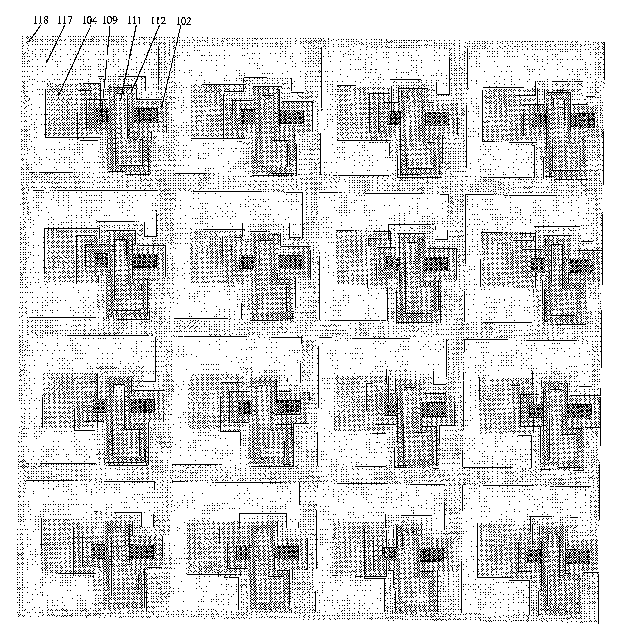
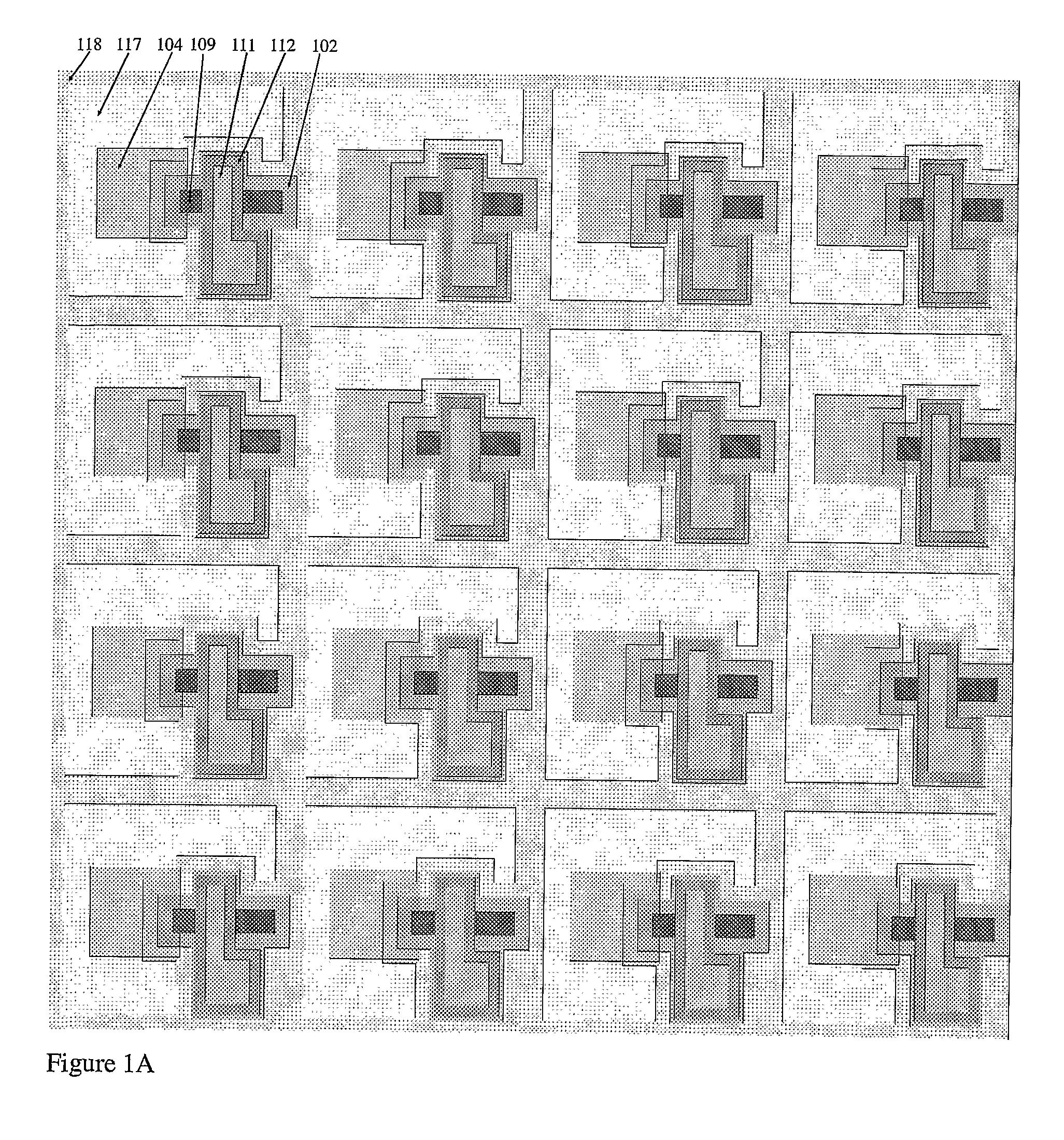
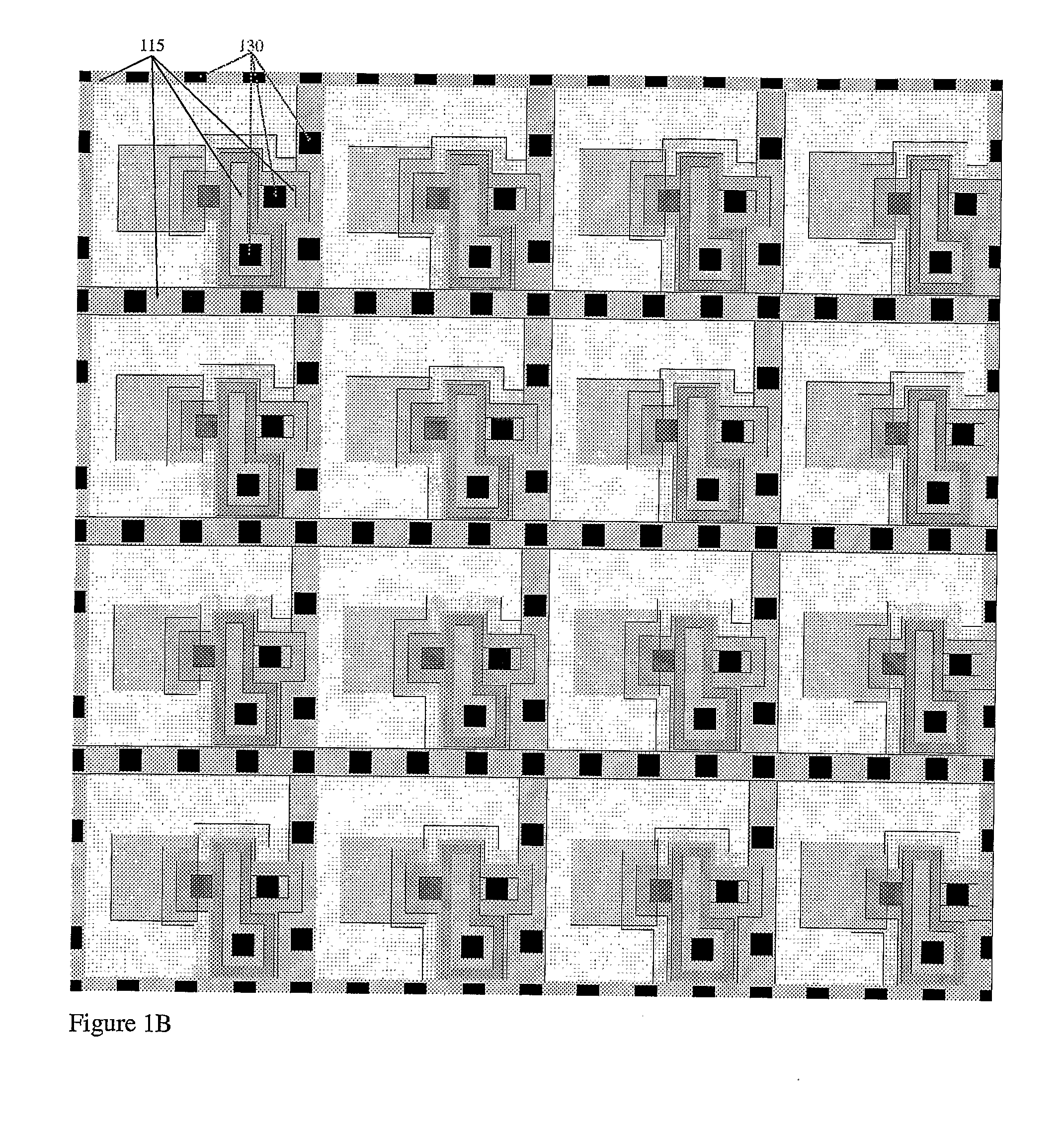
[0032] The present invention is based by the invention of WO 02 / 33755, which discloses a device and process architectures suitable for the monolithic integration of deep sub-micron CMOS technology, including sub-100 nm CMOS technology, with optoelectronic devices having active layers deposited on CMOS active areas. One example of such devices is an Avalanche Photo-Diode (APD) incorporating epitaxial SiGeC layers.

[0033] The device and process architectures disclosed in WO 02 / 33755 show how single-crystal p-type SiGe and / or SiGeC epitaxial films can be epitaxially deposited on n-type CMOS active areas, forming a pn-heterojunction that is separated, by shallow trench isolation (STI), from the neighboring CMOS devices. For this reason it can be run in the avalanche mode, unlike conventional CMOS junctions, thus unlike conventional CMOS photo-diodes. The p-type SiGe and / or SiGeC is the top electrode of the APD and the n-type CMOS active area is the bottom electrode of the APD. The top e...


PUM


Abstract

Several detailed layout designs are disclosed, for the monolithic integration of avalanche devices in large arrays, that can be operated as Avalanche Photo-Diodes (APDs) or Avalanche Light Emitting Diodes (ALEDs) depending only on the applied bias conditions, which can be software-controlled from peripheral circuitry. If the deposited films have direct bandgaps, then the devices can emit light even in the absence of avalanche operation. In particular, the layouts according to the invention comprise a sensor/emitter matrix achieved through the replication of basic Pixel/Lixel cells.

Description

BACKGROUND OF THE INVENTION [0001] The present invention relates to the fabrication of CMOS-based light-sensing and light-emitting devices, and in particular to layouts for the fabrication of such devices. [0002] Conventional CMOS image sensors use of the built-in pn-junction formed by the source / drain and potential-well regions (n-type or p-type) of MOSFETs as the photo-diode. For that reason many important characteristics of the photo-diode are coupled to the design of CMOS devices. CMOS image sensors enable “active pixels”, in which one of more CMOS devices are used for the electronic amplification of the photo-generated signal. The readout process is non-destructive and consists in transferring the photo-generated charges to the gate of a MOSFET whose transconductance translates those charges into a voltage or current. The junction used as storage node must be reset before a subsequent image acquisition. [0003] Other drawbacks of conventional CMOS image sensors include: (1) High...

Claims


Application Information

Patent Timeline
Patent Type & Authority Applications(United States)
IPC IPC(8): H01L31/00
CPCH01L27/146H01L27/14603H01L27/1463H01L27/14643H01L27/156H01L27/14609
Inventor AUGUSTO, CARLOS J.R.P.
Owner QUANTUM SEMICON
Why Eureka
Try Eureka